Electronic device, quantum interference device, atomic oscillator, magnetocardiograph, oscillator, electronic apparatus, moving object, and method of manufacturing electronic device
- Summary
- Abstract
- Description
- Claims
- Application Information
AI Technical Summary
Benefits of technology
Problems solved by technology
Method used
Image


Examples
first embodiment
Atomic Oscillator
[0062]First, an electronic device according to a first embodiment of the invention will be described. In this embodiment, a description will be given of an example in which the electronic device according to the invention is applied to an atomic oscillator (quantum interference device) using a quantum interference effect.
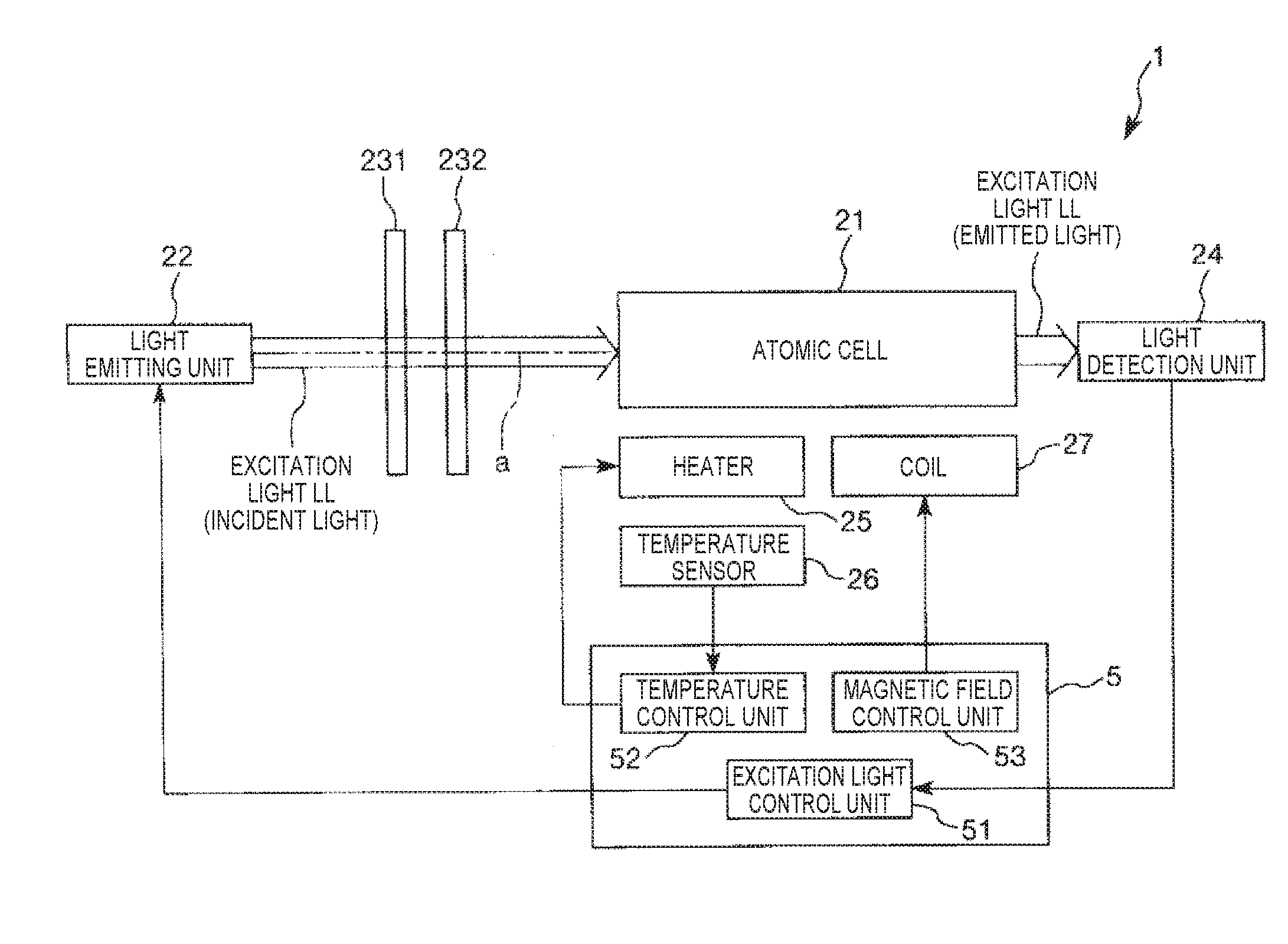
[0063]FIG. 1 is a schematic diagram illustrating an electronic device (atomic oscillator) according to the first embodiment of the invention. FIG. 2 is a diagram illustrating an energy state of an alkali metal, and FIG. 3 is a graph illustrating a relationship between a difference in frequency between two light beams from a light emitting unit and detection intensity in a light detection unit.
[0064]An atomic oscillator 1 illustrated in FIG. 1 is an atomic oscillator using a quantum interference effect.
[0065]As illustrated in FIG. 1, the atomic oscillator 1 includes an atomic cell 21, a light emitting unit 22, optical components 231 and 232, a light ...
second embodiment
[0175]Next, a second embodiment of the invention will be described.
[0176]FIGS. 9A and 9B are diagrams illustrating a getter material, a heat generating portion, and a conductive terminal according to the second embodiment of the invention, FIG. 9A is a plan view, and FIG. 9B is a cross-sectional view taken along line A-A in FIG. 9A.
[0177]This embodiment is the same as the above-described first embodiment except that the arrangement of a getter material of a getter member.
[0178]Meanwhile, in the following description, the second embodiment will be described focusing on differences from the above-described embodiment, and a description of the same matters will be omitted. In addition, in FIGS. 9A and 9B, the same components as those in the above-described embodiment will be denoted by the same reference numerals and signs.
[0179]As illustrated in FIGS. 9A and 9B, a getter member 6A according to this embodiment includes a heat generating portion 61, a pair of getter materials 62A provid...
third embodiment
Crystal Oscillator
[0181]Next, a third embodiment of the invention will be described.
[0182]FIG. 10 is a cross-sectional view illustrating a schematic configuration of an electronic device (crystal oscillator) according to the third embodiment of the invention.
[0183]This embodiment is the same as the above-described first embodiment except that the electronic device according to the invention is applied to a quartz crystal oscillator.
[0184]Meanwhile, in the following description, the third embodiment will be described focusing on differences from the above-described embodiment, and a description of the same matters will be omitted. In addition, in FIG. 10, the same components as those in the above-described embodiment will be denoted by the same reference numerals and signs.
[0185]As illustrated in FIG. 10, a quartz crystal oscillator 1A (electronic device) includes a unit 2A (functional component) in which a quartz crystal vibrator 7, a heater 25A, and a temperature sensor 26A are mou...
PUM
 Abstract
Description
Claims
Application Information