
Transient grating time resolved luminescence measurements

a technology of luminescence measurement and transient grating, which is applied in the field of transient gratings, can solve the problems that cannot be done using any current existing technique, and achieve the effects of optimizing numerical aperture, reducing dispersion, and high numerical aperture optics

Active Publication Date: 2016-12-08
VICTORIA LINK LTD
View PDF1 Cites 5 Cited by
  • Summary
  • Abstract
  • Description
  • Claims
  • Application Information

AI Technical Summary

Benefits of technology

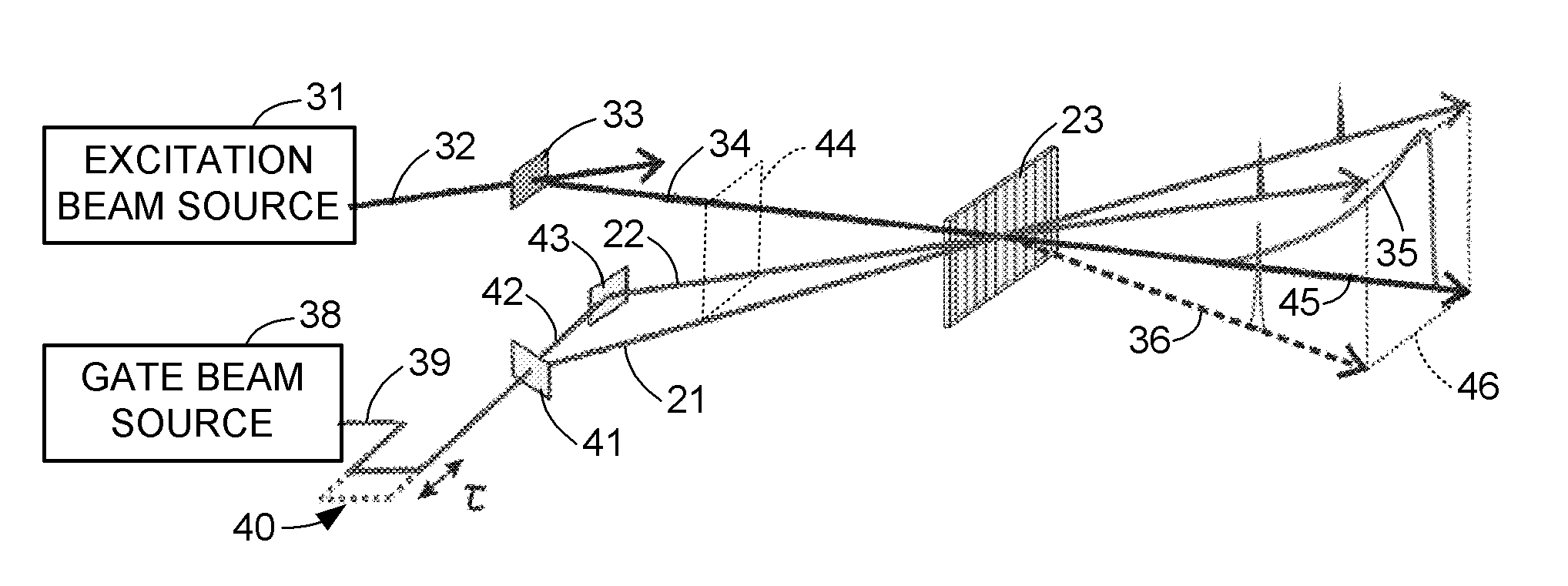
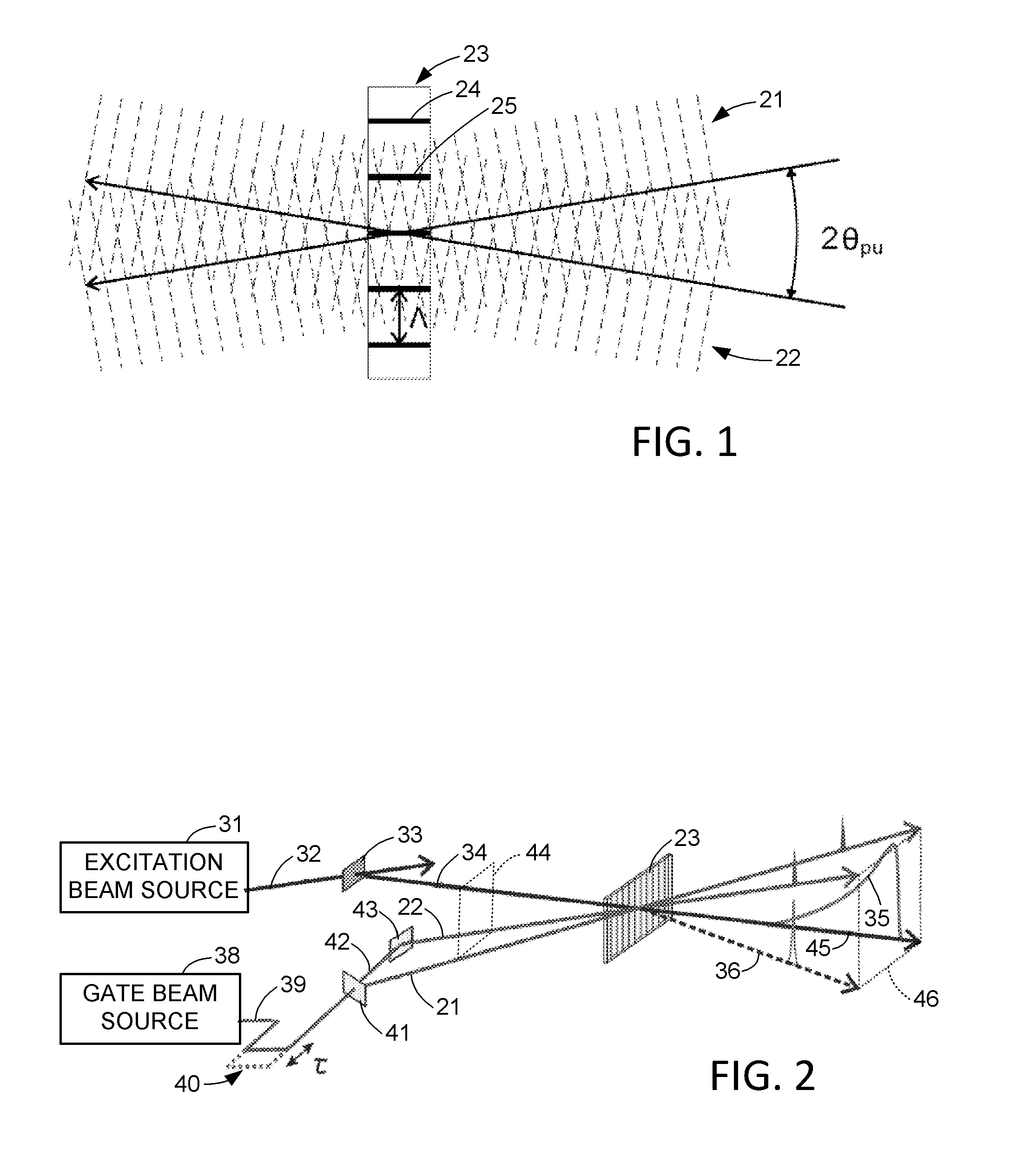
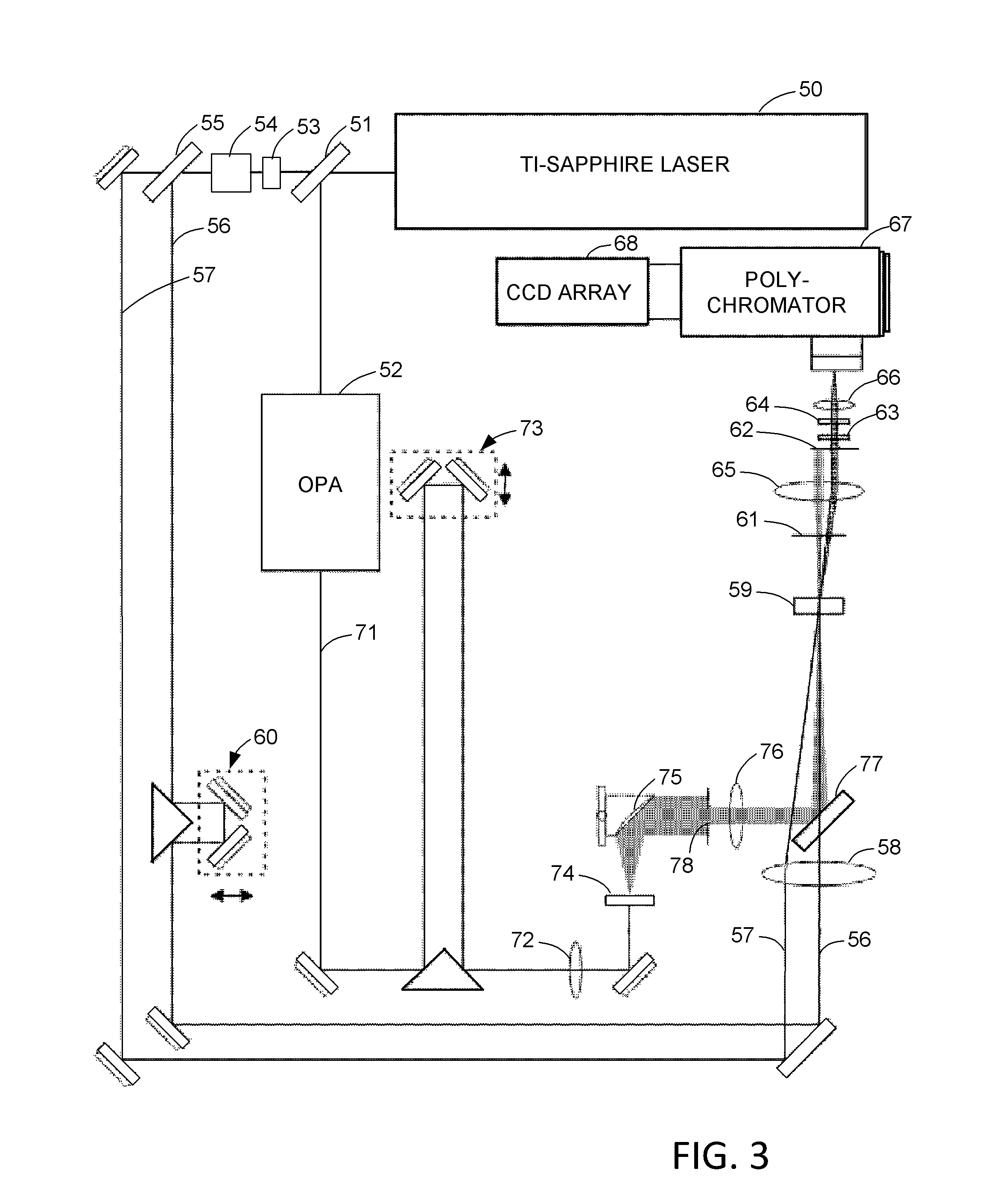
The present disclosure is about a system that uses a transient grating (TG) to capture luminescence images or broadband luminance spectra with high sensitivity and without background noise. The system can detect signals from the UV to IR without changing the optical setup and has a very low background noise to fulfill requirements for high sensitivity, background-free TRPL spectroscopy. The TG provides a higher detection efficiency and without the need for expensive polarizers. The system also has a fast response time and large band gap with smooth surfaces to minimize background noise from undesired scattering of the gate beams and ungated PL. The technical effects of the patent text are improved detection and imaging capabilities with high sensitivity and accuracy for various applications.

Problems solved by technology

Such a technique is expected to be a powerful tool to study ultrafast electronic dynamics with broadband spectral resolution for strongly emissive samples, which cannot be done using any current existing technique.

Method used


Image

  • Transient grating time resolved luminescence measurements
  • Transient grating time resolved luminescence measurements
  • Transient grating time resolved luminescence measurements

Examples


Embodiment Construction

[0026]It will be appreciated that for simplicity and clarity of illustration, where appropriate, reference numerals have been repeated among the different figures to indicate corresponding or analogous elements. In addition, numerous specific details are set forth in order to provide a thorough understanding of the embodiments described herein. However, it will be understood by those of ordinary skill in the art that the embodiments described herein can be practiced without these specific details. In other instances, methods, procedures and components have not been described in detail so as not to obscure the related relevant feature being described. Also, the description is not to be considered as limiting the scope of the embodiments described herein. The drawings are not necessarily to scale, certain parts have been omitted for clarity, and the proportions of certain parts have been exaggerated to better illustrate details and features of the present disclosure. For example, FIG....


PUM


Abstract

A transient grating (TG) is used as an optical gating element with sub-picosecond time resolution for luminescence measurements from a photo-detector array. The transient grating is formed in a gate medium by one or more pulsed gate beams. For photoluminescence measurements such as photoluminescence spectroscopy or imaging, a source is excited by a pulsed excitation beam, and the pulsed gate beams are synchronized to the pulsed excitation beam with an adjustable delay between the excitation of the source and the formation of the TG. Moreover, a source or its spectra can be imaged at two different regions of the photo-detector array at two different times spaced in time by a selected duration of time with sub-picosecond resolution over a range of a nanosecond or more. A beam from the source is deflected to the different regions by changing the frequency or geometry of the pulsed gate beams.

Description

TECHNICAL FIELD[0001]This disclosure relates to the use of transient gratings as optical gates for time resolved luminescence measurements, such as time resolved photoluminescence (TRPL) spectroscopy and time resolved luminescence imaging.BACKGROUND ART[0002]Photoluminescence (PL) spectroscopy is an essential tool to study photo-excited electronic processes [Lakowicz, Joseph R., ed. Principles of fluorescence spectroscopy. Springer, 2009.]. Among various PL spectroscopy techniques, time-resolved photoluminescence (TRPL) spectroscopy has been shown to be a powerful tool to study photochemistry, photophysics and photobiology [Fleming, Graham. Chemical applications of ultrafast spectroscopy, (1986). Beechem, Joseph M., and Ludwig Brand, Annual review of biochemistry 54.1 (1985): 43-71.]. The advantages of TRPL include high sensitivity and selectivity. With careful experimental design, TRPL can be performed as a background free measurement to probe the weak interaction of the excitation...

Claims


Application Information

Patent Timeline
IPC IPC(8): G01J1/42
CPCG01J1/4228G01N21/636G01N21/6408G01N21/65G01N2201/061G01N2201/0696G01J2003/4424G01J3/2889G01J3/4406G01J3/0232
Inventor HODGKISS, JUSTIN M.CHEN, KAI
Owner VICTORIA LINK LTD
Learn More