Consumer Product System

a product system and consumer technology, applied in the field of consumer product systems, can solve the problems of increasing the cost and power consumption of the device, creating confusion, ugly dummy buttons and blanking plates, etc., and achieve the effects of reducing the risk of product damage, reducing the retention strength, and improving the overall user experien

Inactive Publication Date: 2016-12-15
ZEN ECOSYST IP PTY LTD
View PDF30 Cites 14 Cited by
  • Summary
  • Abstract
  • Description
  • Claims
  • Application Information

AI Technical Summary

Benefits of technology

[0076]The magnetic connection is not subject to “creeping” that may be common in other retention methods that utilize plastic features or moulded plastic housings. It is advantageous to avoid creeping because, in time, creeping deteriorates and reduces the retention strength applied to these plastic mating parts.
[0077]The magnetic connection is not subject to damage by accidental hits or drops of the instrument. The housings of preferred embodiments have been designed so that they connect in a way that makes it very difficult to dislodge the front housing by bumping or knocking the unit.
[0078]Maintaining an aesthetically pleasing, easy and intuitive to use unit that is durable is important to the success of home consumer products. In this respect, the magnetic connection of preferred embodiments eliminates the possibility of a non-functional unit due to wear or damage of a crucial mating feature.
[0079]As the system of preferred embodiments is self aligning and doesn't require prior learning by the user, it further reduces risk of damaging of the product and it improves the overall user experience by reducing the hassles involved with the installation of a new product.

Problems solved by technology

Dummy buttons and blanking plates are ugly and may create confusion.
This makes the user interface more intuitive but increases the cost and power consumption of the device.
Other designs may provide allowance for labelling of button panels, but this is usually done using visually unappealing labels which may not complement the interior design and look of the room (e.g. in the case of simple mechanical switches) or alternatively requires high-cost, high power LCD screens.
Consumers are reluctant to purchase and install home automation technology that does not fit, ruins or spoils the look and feel of the interior design of their homes.
Consumers who purchase and install “smart” devices like home automation controllers and button panels will not necessarily have the time or ability to undertake the full configuration of these device.
Further to the above, the inventor has recognised problems and disadvantages of conventional retention methods for wall mounted devices like thermostats that use features such as snaps, clips, lugs or bayonets usually moulded in plastic housings to retain two mating parts that typically comprise a wall mounted part and a removable front cover or front housing part.
Accordingly, disadvantages recognised by the inventor in the prior art stem from, a requirement for guiding one or both parts together through predetermined movements to either attach or remove the front housing.
There is also the risk of damaging these mechanical structural retention features by missing the right installation path or routes, or in other words inadvertently guiding the front housing part off course leading to a misalignment when engaging or disengaging with the wall or mounted part.
There exists also a risk of potentially breaking any structural retention features by dropping or hitting the instruments where structural retention features all present protruding parts which are prone to damage.
There is also a loss of retention strength due to “creeping” of plastic materials.
Le describes and identifies problems in that wall boxes generally suffer from various disadvantages related to mounting.
For instance, problems can arise if the wall box is skewed in any way after it has been mounted.
In such a situation, the resulting light switch, light switch plate, or other device positioned in the wall box will appear to be similarly skewed resulting in an un-aesthetic appearance.
Additionally, if the depth of the wall box mounting in the wall is too deep, the supplied screws may be too short to affix the light switch, light switch plate, or other device to the wall box.
Further, if the mounted wall box is not parallel to the wall's surface, the mounting screws can become cross threaded, because the screw is not received perpendicularly in a receiving nut or tapped hole, leading to eventual failure of the mounting system.
Problems may also arise in situations where a devices such as an infrared receiver or an infrared plate, is positioned in a skewed manner in the wall box.
For example, the performance of the device can be affected if any equipment in communication with the device cannot adequately communicate because the device is not mounted properly.
It is considered that the device and system of Le involves unnecessary complexity in its requirement for the arrangement to include three components and, for example, at least the need to have the base plate inserted within a wall box.
The problem(s) addressed by Helms et al are that connecting electrical components to a power source can be cumbersome and, additionally, replacing currently installed housings for electronic equipment can be a difficult and expensive task.

Method used


Image

  • Consumer Product System
  • Consumer Product System
  • Consumer Product System

Examples


Embodiment Construction

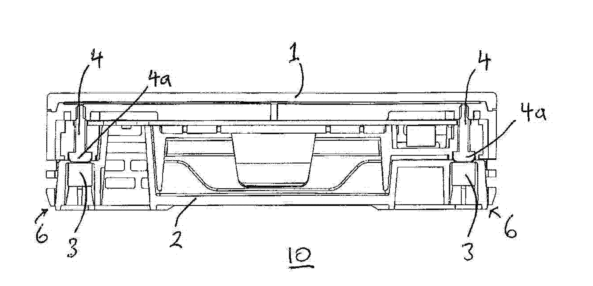
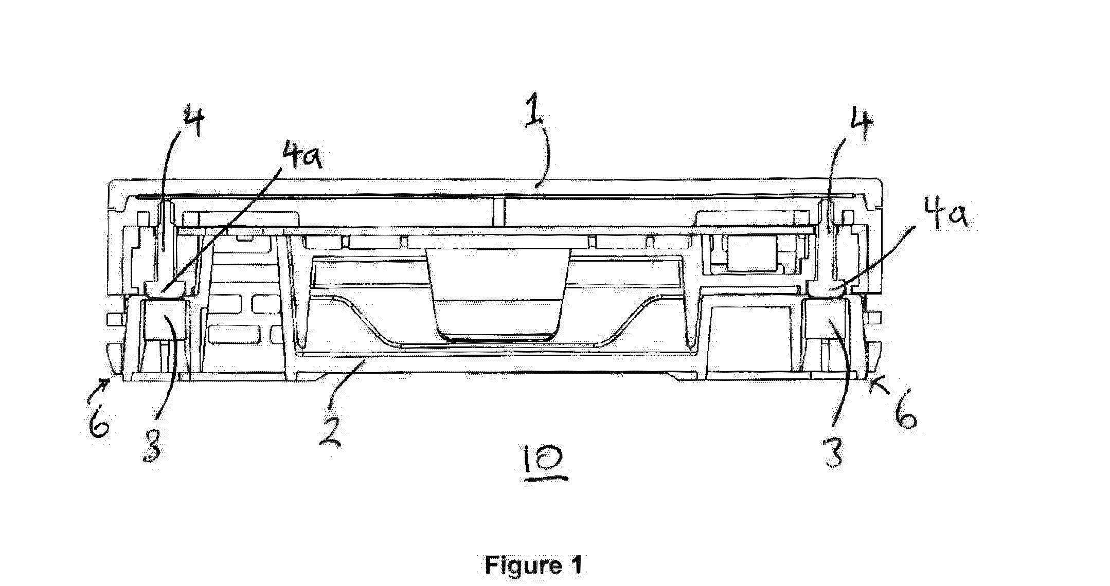
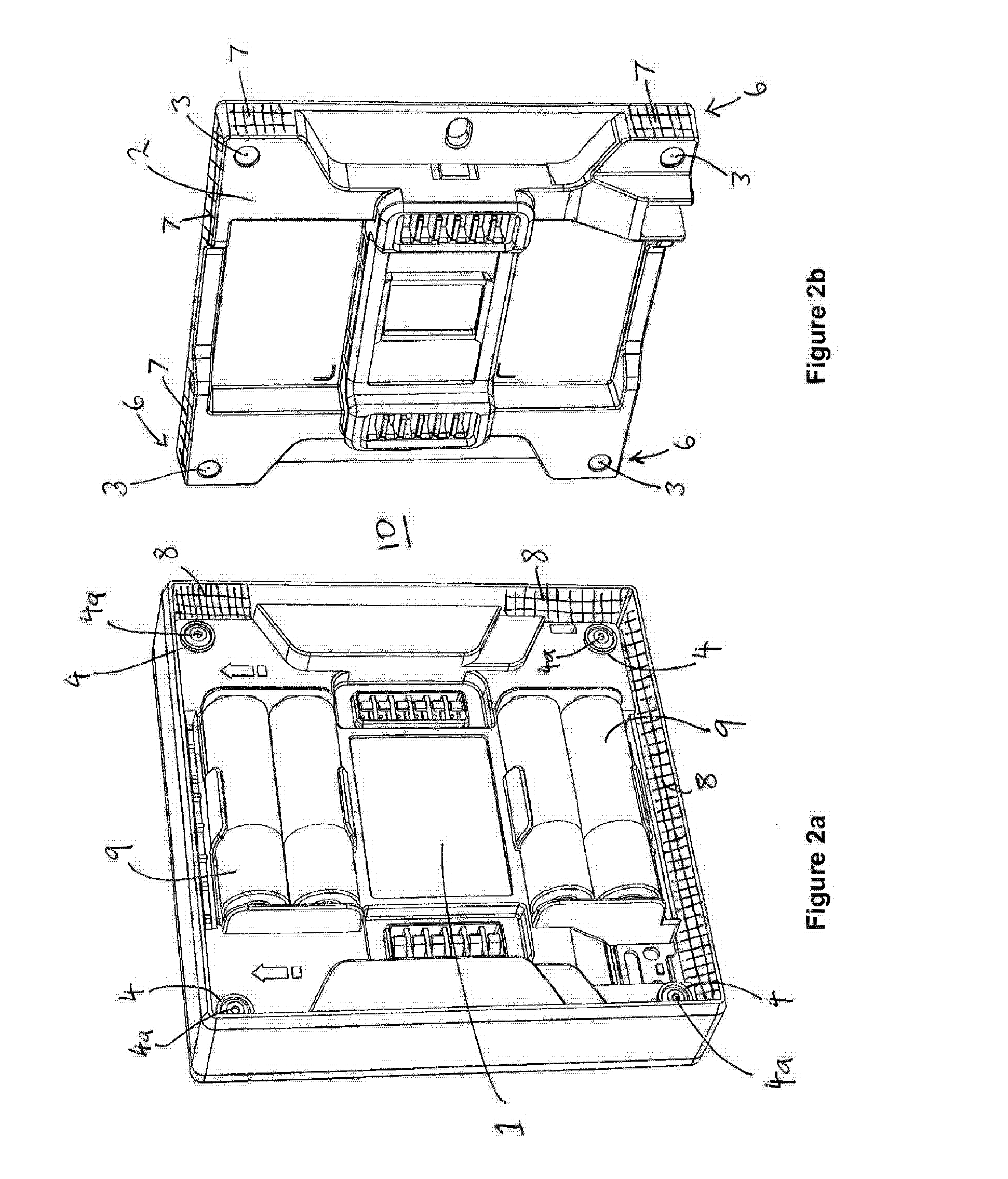
[0092]In one embodiment the present invention addresses the problems associated with retention means for wall mounted devices, like a thermostat, that commonly utilise plastic fastening mechanisms to retain two mating parts, ie a front housing to a wall mounted portion. The problems arise with these mechanical mountings from one or more of the following: a need for guiding the two mating parts through predetermined movements to engage; the risks of damaging the retention features by missing (overshooting etc) the correct installation path or route; the risk of breaking the retention features by dropping or hitting the instruments, noting that conventional retention features all present protruding parts which are prone to physical damage and; the loss of retention strength due to ‘creeping’ of plastic materials.

[0093]As disclosed and with reference to the accompanying drawings, a preferred solution offered by the inventor for a wall mounted thermostat device, denoted generally as 10,...


PUM


Abstract

A user interface with a display region having an array of configurable button elements operatively connected to a processor adapted to operate in accordance with a predetermined instruction set to activate a predetermined set of the button elements corresponding to a matching set of device nodes to be in operative connection for a user to control via the user interface. There is also a method of releasably retaining a first portion with a second portion of a mounted electronic device, the method including the steps of: locating the first portion in non-contacting proximity to the second portion of the electronic device such that at least one magnet located in one of the first or second portions exerts attractive force on at least one ferrous component of the other of the first or second portions such that the magnetic force guides the first portion into self-aligning contact with the second portion.

Description

RELATED APPLICATIONS[0001]This application claims priority to Australian Provisional Patent Application No. 2014900625 in the name of Planet Intellectual Property Enterprises Pty Ltd, which was filed on 26 Feb. 2014, entitled “Device Retention Means” and to Australian Provisional Patent Application No. 2014900632 in the name of Planet Intellectual Property Enterprises Pty Ltd, which was filed on 26 Feb. 2014, entitled “Configurable User Interface” and the specifications thereof are incorporated herein by reference in their entirety and for all purposes.FIELD OF INVENTION[0002]The present invention relates to the field of consumer product systems. It will be convenient to hereinafter describe the invention in relation to a wall mounted consumer product control device such as a thermostat, a lighting or appliance control panel, a relay control panel, a window covering control panel or, in another form a lighting switch, however it should be appreciated that the present invention may n...

Claims


Application Information

Patent Timeline
Patent Type & Authority Applications(United States)
IPC IPC(8): F16B1/00F24F11/00H05K5/02G05B15/02H05K5/00
CPCF16B1/00G05B15/02H05K5/0004F16B2001/0035F24F11/0086G05B2219/2642G05B2219/2614H05K5/0217G06F3/0238H02G3/10H02G3/14F24F11/30F24F11/52F16B2200/83
Inventor DRUCE, BENJAMINSEBASTIANI, MARCOSTIMSON, JEREMY PHILLIPSMITH, ROHANLOSCHER, ALINA
Owner ZEN ECOSYST IP PTY LTD
Why Eureka
Try Eureka