
Power control module with improved start requirements

a power control module and start requirement technology, applied in the direction of process and machine control, pulse technique, instruments, etc., can solve the problems of increasing the start up time needed to charge up, affecting the overall circuit operation, and reducing the board spa

Active Publication Date: 2016-12-15
SANKEN ELECTRIC CO LTD
View PDF13 Cites 27 Cited by
  • Summary
  • Abstract
  • Description
  • Claims
  • Application Information

AI Technical Summary

Benefits of technology

The patent describes a power control device for an external circuit that can adjust the power supply to the circuit based on the input voltage. The device includes a control unit, a drive unit, and a startup circuit. The startup circuit generates a power supply based on the input voltage and provides it to the control unit and the drive unit. The control unit then drives the external circuit, which includes a PFC and a DC-DC converter. The device can also operate in different modes based on the drive power supply voltage and can detect and switch the current supplied to the control unit and the control unit based on the drive power supply voltage. The device can also be used in a three circuit apparatus with sequential power up capability. The technical effects of the patent are improved power control and flexibility in power supply options for external circuits.

Problems solved by technology

A problem of power control circuits arises when a microprocessor needs initial power supplied via a Vcc pin in parallel with a capacitor, and when other circuits also need typically higher power to start.
This delays overall circuit operation because the microprocessor has to regulate and control the other circuits, while at the same time waiting to start control while the other circuits are competing for power up current.
The additional power demands put pressure on designing a larger Vcc capacitor, with commensurate decrease in board space, increased cost and increased start up time needed to charge up the capacitor to a suitable voltage.
In some cases an analog power supply IC is used for power in the start up circuit, which adds further expense and complexity.
Accordingly one problem in this field is the need for a more efficient start up power system that can minimize board space, cost, complexity and start up time.

Method used


Image

  • Power control module with improved start requirements
  • Power control module with improved start requirements
  • Power control module with improved start requirements

Examples


example 1

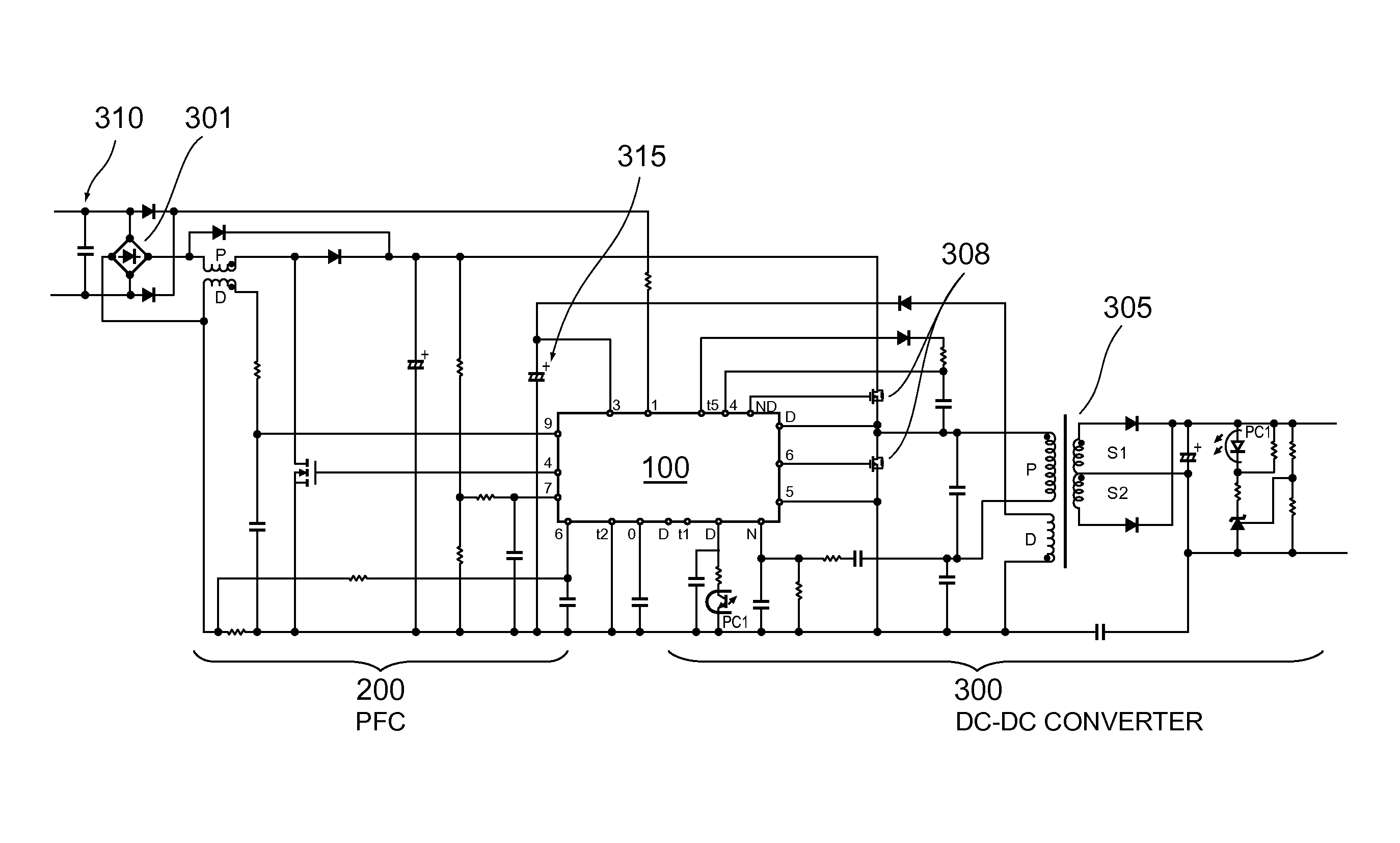
[0068]As implemented in the circuit diagram of FIG. 8, FIG. 9 shows timing for a desirable start up embodiment.

[0069]As seen from the structure of FIG. 8, upon switching on, PFC output voltage increases. At first a switching element in PFC 200 is driven to a constant on duty cycle because of the voltage increase. When the PFC output voltage exceeds a target voltage, feedback control of the PFC commences. Accordingly, in the start circuit, electric current is supplied only as necessary for control of the PFC and this lowers the initial starting current demand. For example, current is supplied only for necessary conditions (Sysc) to carry out a start sequence. The term Sysc refers to a system controller that controls the sequence to boot the circuit blocks included in the controller. Thus power consumption of the control unit is reduced by limiting the electric power supply for the CPU performing system processing. Such processing may include, for example, abnormal condition detection...


PUM


Abstract

Circuits and devices are described that provide power to appliances and other devices via a power correction circuit and an LLC converter, which may for example include resonant series converters and flyback converters. The circuits and devices economize on board space, part size and power start up time by separately powering up the controller circuit portion prior to powering up the LLC converter.

Description

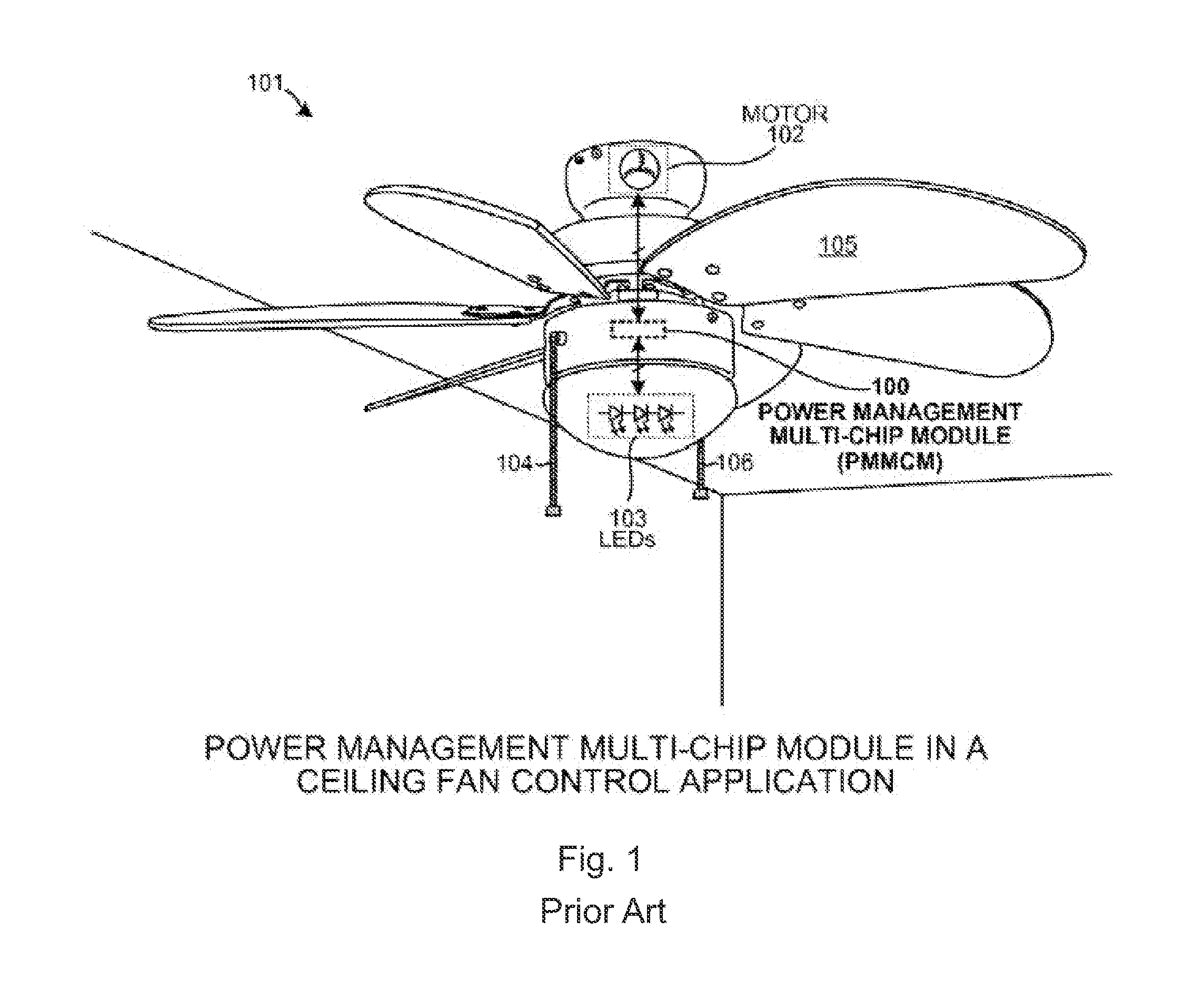
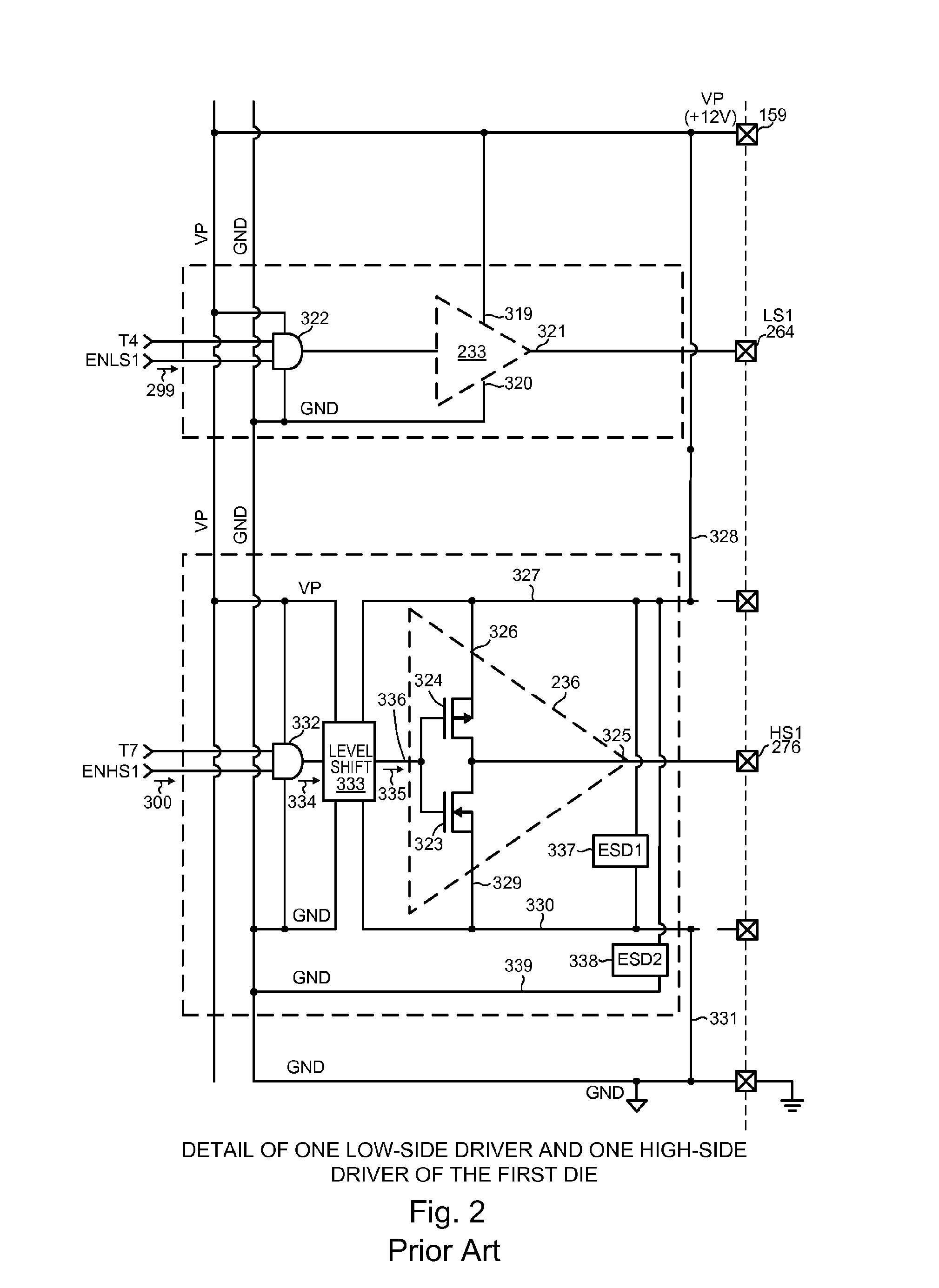
FIELD[0001]Embodiments relate to power control circuits, particularly for appliances.BACKGROUND[0002]Modern appliances such as electric fans, other AC motors, LEDs, and other DC powered devices work best when supply power is controlled to optimize parameters such as power factor, phase differences and voltage differences. See for example US No. 20140125266 (Huynh et al.), which teaches a processor-controlled high and low side driver circuitry such as for driving inductive loads. Huynh discloses a combination of low and high voltage dies in a power management multi-chip module (PMMCM) containing two dies for driving a fan, as shown in FIG. 1 which is a reproduction of Huynh's FIG. 2 used for explaining this prior art reference.[0003]One die contains a pulse-width modulator (PWM) and other components that include low-side drivers. The second die contains the ultra-high voltage high-side drivers that supply drive signals to the external high-side transistors. External low-side transist...

Claims


Application Information

Patent Timeline
IPC IPC(8): H02M3/335H02M1/36H02M1/42
CPCH02M3/33546H02M1/36H02M1/4208H02M1/42H02M3/33515H02M3/33523H02M1/4225H02M3/33507H03K2217/0036Y02B70/10H02M1/0006
Inventor NAKANO, TOSHIHIRO
Owner SANKEN ELECTRIC CO LTD
Learn More