Methods for Providing a Durable Solar Powered Aircraft with a Variable Geometry Wing

a solar energy and variable geometry technology, applied in the field of solar energy aircraft, can solve the problems of rocket launch itself being a non-negligible risk, unable to recover and change orbits, and reducing the efficiency of solar energy storage, so as to achieve the effect of increasing the efficiency of photovoltaic cells, increasing reliability and safety in long-distance flights, and sufficient rigidity

Active Publication Date: 2016-12-22
KAREM AIRCRAFT INC
View PDF3 Cites 20 Cited by
  • Summary
  • Abstract
  • Description
  • Claims
  • Application Information

AI Technical Summary

Benefits of technology

[0022]The inventive subject matter provides apparatus, systems and methods that provide a solar powered aircraft capable of long duration flights at high altitude and in latitudes greater than 30° N and 20° S. The aircraft is of rigid, molded construction, and includes a segmented wing. Individual wing segments are joined by hinges adjustable to positive and negative dihedral angles during flight. This permits orientation of photovoltaic cells towards the horizon when the sun is at a low angle, thereby increasing the efficiency of the photovoltaic cells. The aircraft's molded construction provides sufficient rigidity to permit the aircraft to fly through inclement weather conditions. Reliability and safety in long duration flights is further increased by reliance on free flight (with no active control) for greater than 90% of the flight, which reduces wear on active control surfaces. Aircraft of the inventive concept are capable of flight durations of 2 months to 5 years at altitudes in excess of 50,000 feet and at latitudes between 40° N BS 30° S.

Problems solved by technology

The preparation and delivery costs of such satellites represents a considerable expense, however, and rocket launches themselves represent a non-negligible risk.
While satellites have the advantage of requiring no significant energy in order to remain in orbit for years, they lack the ability to recover and to change orbits as may be required to modify the communication equipment or the serviced area.
Additionally, while the satellites offer wide area coverage their great communications distance results in the need to use high transmission power and relatively narrow antenna apertures, which in turn results in communications time delays.
Because of their required high launch energy and extreme system reliability, satellites present substantially higher initial costs than aircraft.
Solar energy, however, is a relatively diffuse source that can limit the power available to propel the aircraft.
In addition, reliance on solar power can restrict the latitude and / or time of year that such aircraft can operate effectively.
Unfortunately, such extremely flexible structures are relatively fragile.
The Helios was lost in an inflight failure, with aircraft loss due to wind gusts on Jun. 26, 2003.
Long duration solar powered aircraft are also hampered by the relatively low energy density of regenerative batteries and regenerative fuel cells required to power the craft at night.
Flying at high altitude is additionally challenging in this regard, as the low air density increases the power required for propeller driven aircraft (e.g. by a factor of 3× relative to sea level at 56,000 ft and a factor of 4× relative to sea level at 69,000 ft).
Additionally, the increased dynamic viscosity at high altitude (resulting in reduced Reynolds numbers) results in reduced aerodynamic performance in terms of aircraft lift / drag ratio and propeller efficiency for slow flying aircraft.
A key challenge for a solar powered aircraft to provide an acceptable market entry is the ability of the aircraft to collect solar energy at low sun angles, such as in winter and early and late in the day.
Such approaches, however, are not viable for the intended use of replacing orbiting communications satellites.
This increases expense and design complexity, and provides numerous opportunities for component failure.
This results from the additional parasitic drag of vertical surfaces beyond those necessary for efficient flight, resulting in increased power requirements.
In addition, such vertical surfaces can negatively impact aircraft stability in inclement weather.
Unfortunately, as demonstrated by the loss of Helios aircraft due to weather, such a flexible wing does not provide an aircraft that is sufficiently rugged for long duration flight.

Method used


Image

  • Methods for Providing a Durable Solar Powered Aircraft with a Variable Geometry Wing
  • Methods for Providing a Durable Solar Powered Aircraft with a Variable Geometry Wing
  • Methods for Providing a Durable Solar Powered Aircraft with a Variable Geometry Wing

Examples


Embodiment Construction

[0036]The following description includes information that may be useful in understanding the present invention. It is not an admission that any of the information provided herein is prior art or relevant to the presently claimed invention, or that any publication specifically or implicitly referenced is prior art.

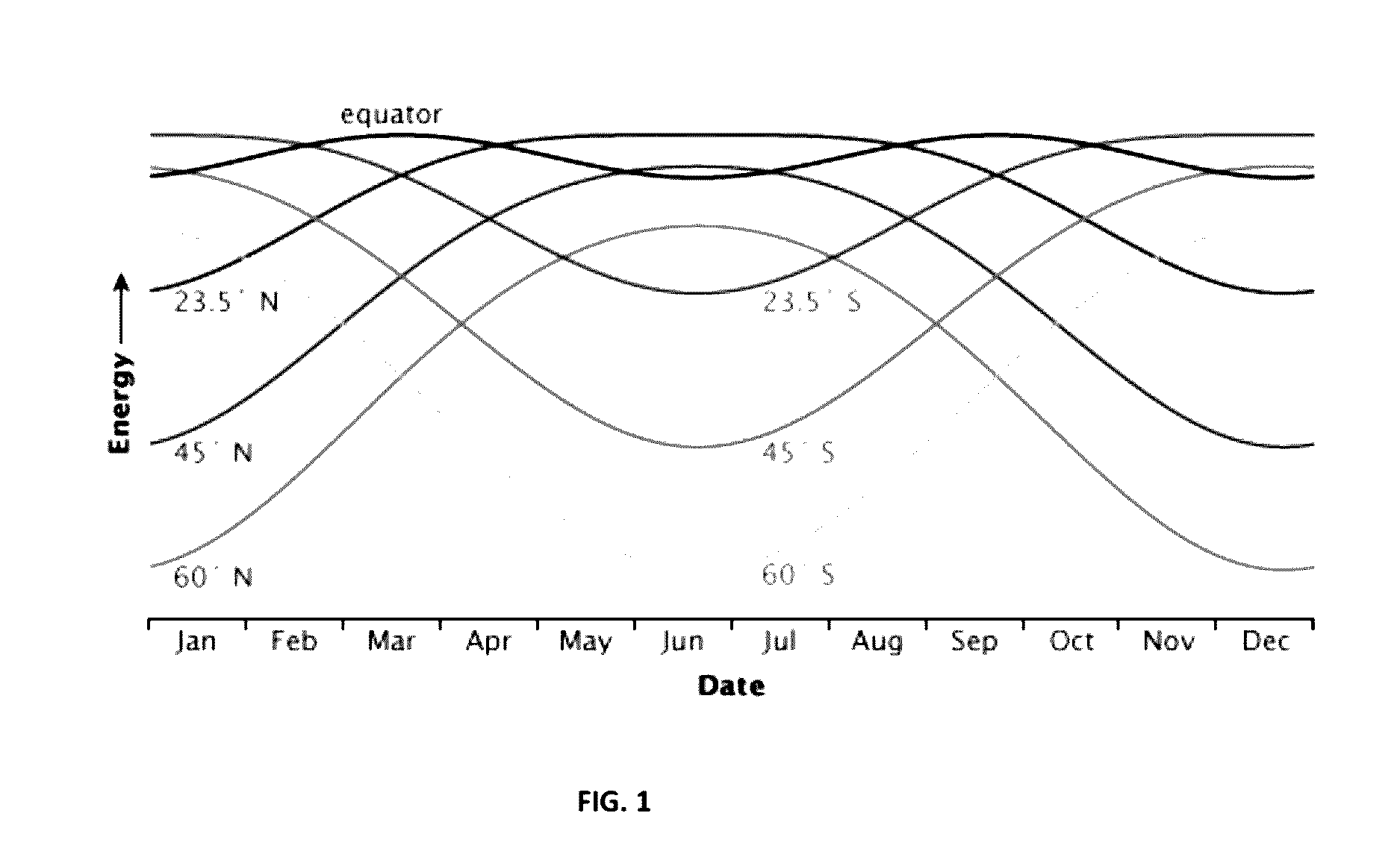
[0037]High altitude, long flight endurance aircraft present an attractive alternative to satellites in telecommunications networks. One obstacle to the development of these is a power source that can sustain uninterrupted flight for weeks, months, or years without the need for active refueling. Solar power provides a potential solution, but presents challenges beyond the obvious day / night cycle. As shown in FIG. 1 the solar energy available in kilowatt per square meter varies as a function of time of year and geographical elevation (i.e. latitude). It is apparent that in the stratosphere (i.e. above the weather) significant solar energy is available in mid-winter at elevati...


PUM


Abstract

Methods of manufacturing and operating a solar powered aircraft having segmented wings that can be reconfigured during flight to optimize collection of solar energy are described. The aircraft have rigid construction that is resistant to inclement weather and is configured to rely on free flight control at high altitude and under conventional conditions, thereby providing flight duration in excess of 2 months. The aircraft is particularly suitable for use as part of a telecommunications network.

Description

[0001]This application claims the benefit of U.S. Provisional Application No. 62 / 152,747, filed Apr. 24, 2015, U.S. Provisional Patent Application No. 62 / 120369, filed Feb. 24, 2015, and U.S. Provisional Patent Application No. 62 / 120,361, filed Feb. 24, 2015. These and all other referenced extrinsic materials are incorporated herein by reference in their entirety. Where a definition or use of a term in a reference that is incorporated by reference is inconsistent or contrary to the definition of that term provided herein, the definition of that term provided herein is deemed to be controlling.FIELD OF THE INVENTION[0002]The field of the invention is aircraft, particularly solar powered aircraft.BACKGROUND[0003]Orbiting and geosynchronous satellites are in wide use for communication between ground communications hubs and directly between communication users. The revenue of the satellite industry exceeded $200 B in 2014, and over 400 satellites are currently in geosynchronous orbits.[...

Claims


Application Information

Patent Timeline
Patent Type & Authority Applications(United States)
IPC IPC(8): B64C3/42B64C39/02B64D27/24B64F5/00G05D1/00
CPCB64C3/42B64F5/0009G05D1/0011G05D1/0088B64C2201/021B64C39/024B64D2211/00B64C2201/122B64C2201/042B64D27/24B64C3/16B64C11/28H02S10/40H02S40/38B64F5/10H02S20/30Y02E10/50Y02T50/10Y02T50/50Y02T50/40Y02T50/60Y02E70/30B64U50/34B64U30/10B64U10/25B64U2101/20B64U50/19B64U50/13
Inventor KAREM, ABETIGNER, BENJAMIN
Owner KAREM AIRCRAFT INC
Why Eureka
Try Eureka