
Aircraft structure with solar energy capture capacity

a technology of solar energy and aircraft, applied in the direction of solar panel attachments, transportation and packaging, energy-saving board measures, etc., can solve the problems of obvious aircraft penalty, complex implementation, cost or weight, etc., and achieve the effect of reducing the number and time, simple maintenance, and easy adaptation

Inactive Publication Date: 2016-12-22
EURON AERONAUTIC DEFENCE & SPACE +1
View PDF11 Cites 4 Cited by
  • Summary
  • Abstract
  • Description
  • Claims
  • Application Information

AI Technical Summary

Benefits of technology

This patent describes a flexible polymer layer that allows an assembly to deform in the heat and stress conditions of an aircraft. Compared to current solutions for protecting against lightning strikes, this results in reduced installation and maintenance time and effort.

Problems solved by technology

Such a network of bundles of electrical cables is obviously a source of penalty for the aircraft, whether in terms of costs or weight.
Furthermore, the arrangement of such a network of bundles of electrical cables presents the drawbacks of complex implementation, ofincreased complexity in the operations of installing and maintaining these bundles of electrical cables.
Furthermore, since there is a relatively high number of these systems and they are heavy energy consumers, the electrical power source has to supply a not inconsiderable electrical power, which is also a source of penalty in terms of costs and weight.

Method used


Image

  • Aircraft structure with solar energy capture capacity
  • Aircraft structure with solar energy capture capacity

Examples


Embodiment Construction

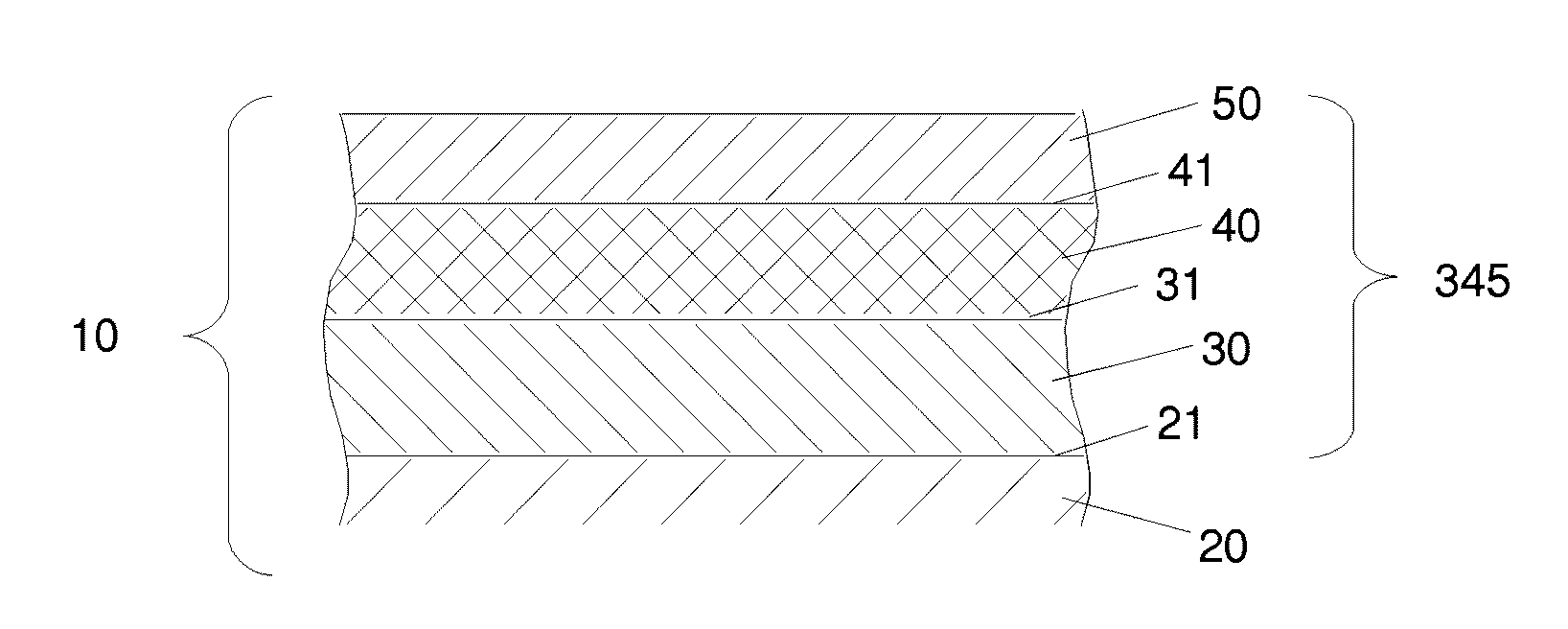
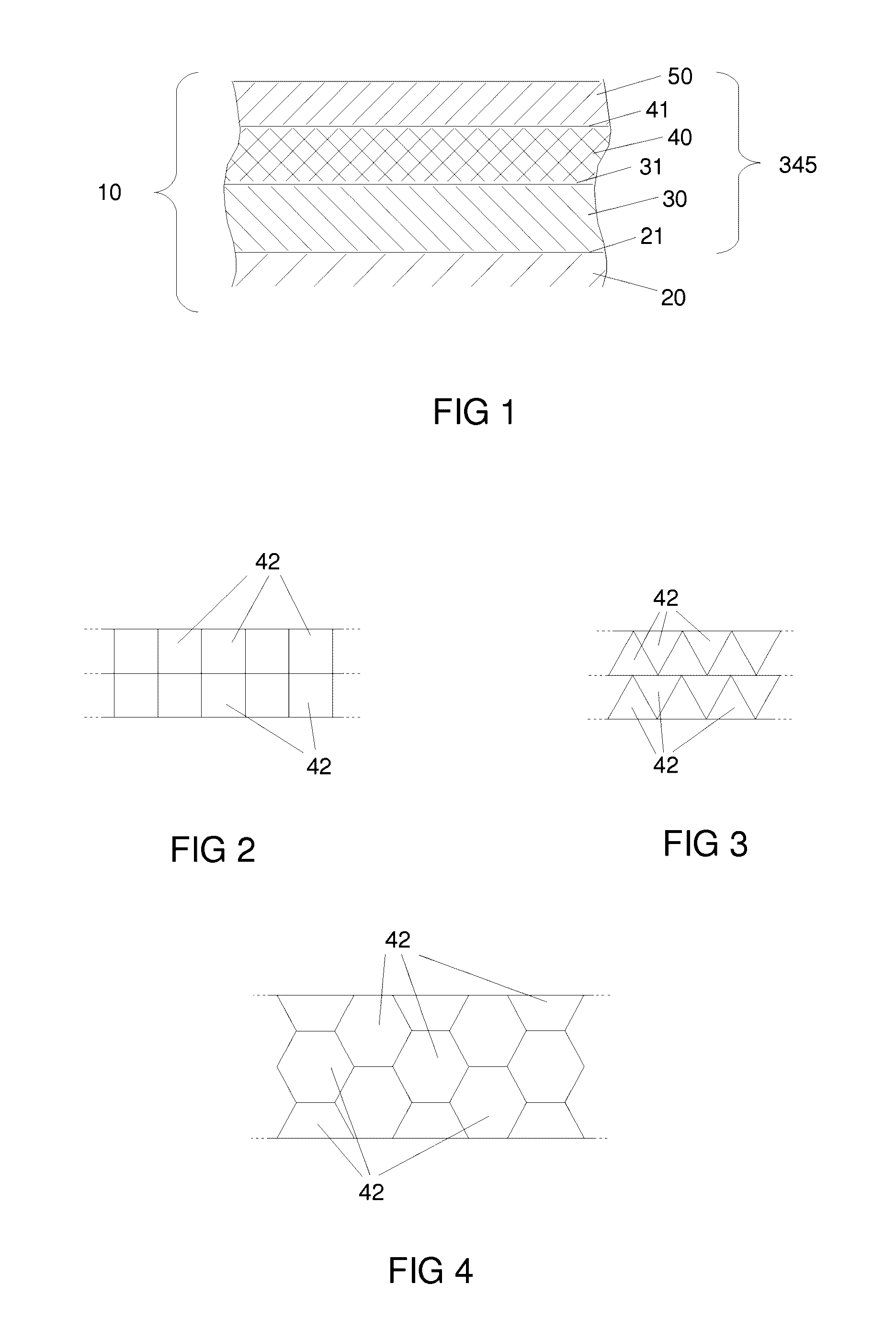
[0074]An exemplary aircraft structure 10 according to the invention is illustrated schematically in FIG. 1. FIG. 1 shows a locally flat aircraft structure by way of illustration without this being in any way limiting of the invention.

[0075]In this FIG. 1, the relative thicknesses of the different layers of this aircraft structure have been chosen by way of example, and so as to clearly show each of these layers, and these relative thicknesses should in no way be considered as limiting or even representative of a real multilayer assembly.

[0076]An aircraft structure 10 according to the invention is made of composite material and mainly comprises a structural part 20 comprising mineral or organic fibers held in a hard organic resin.

[0077]For example, such a structural part 20 comprises stacked plies of glass, Kevlar® or carbon fiber, woven or unidirectional, held in a matrix of a polymer material such as an aramid.

[0078]The aircraft structure described is for example a fuselage without...


PUM


Abstract

An aircraft structure (10), in particular the fuselage, nacelles or wings, includes, over all or part of an outer surface (21) that may undergo lightning impacts, a layer of flexible polymer (30), a photovoltaic film (40) and a protective layer (50) protecting the photovoltaic film. This aircraft structure primarily has a solar energy capture capacity making it possible to meet the needs of an aircraft as well as an ability to protect against the effects of lightning.

Description

FIELD OF THE INVENTION[0001]The present invention relates to the energy supply for aircraft. More particularly, it relates to an aircraft structure with solar energy capture capacity.[0002]The invention offers a particular advantage for aircraft structures made of composite material.STATE OF THE ART[0003]The current aircrafts comprise an embedded electrical power source intended to produce electrical energy on board the latter to make it possible to power, whether on the ground or in flight, different systems consuming electrical power.[0004]These systems, generally remote from one another and from the electrical power source, are distributed throughout the aircraft, from the cockpit to the tail of the airplane, by passing through the wings.[0005]Among the systems that require an electrical power supply remote from the electrical power source, there are, by way of illustrative example, the flashing lights situated at the ends of the wings.[0006]To reach and individually power each o...

Claims


Application Information

Patent Timeline
Patent Type & Authority Applications(United States)
IPC IPC(8): B64D33/00H01L31/049H01L31/18H01L31/0392
CPCB64D33/00H01L31/03926B64D2211/00H01L31/1876H01L31/049H01L31/048H01L31/0445Y02E10/50Y02T50/50B64D27/353
Inventor RIVES, BERTRANDPERES, GILLESPORTE, ALAIN
Owner EURON AERONAUTIC DEFENCE & SPACE
Learn More