
Visible light communication system and method and related device

a technology of communication system and light source, applied in the field of communication, can solve the problem that the inversion condition of output level may be significantly affected by ambient ligh

Active Publication Date: 2016-12-22
HANGZHOU SHINYEASY TECH CO LTD
View PDF3 Cites 0 Cited by
  • Summary
  • Abstract
  • Description
  • Claims
  • Application Information

AI Technical Summary

Benefits of technology

The invention provides a visible light communication system and method that can adapt to different ambient light levels, making it more robust against interference and improving the quality of communication. It achieves this by filtering the voltage amplitude signal to suppress the amplitude of the voltage signal around the frequency range of the visible light signal, and using this filtered voltage amplitude signal as a reference voltage that can vary with varying ambient light. This reference voltage is then used to convert the visible light signal into a level signal, resulting in a more stable communication. Overall, this system and method improve the adaptability, robustness, and quality of visible light communication.

Problems solved by technology

However in the existing visible light communication system typically the output voltage of the photoelectric conversion device is compared by a differential amplification circuit with constant voltage to output a level signal, so that an inversion condition of the output level may be significantly affected by ambient light.

Method used


Image

  • Visible light communication system and method and related device
  • Visible light communication system and method and related device
  • Visible light communication system and method and related device

Examples


first embodiment

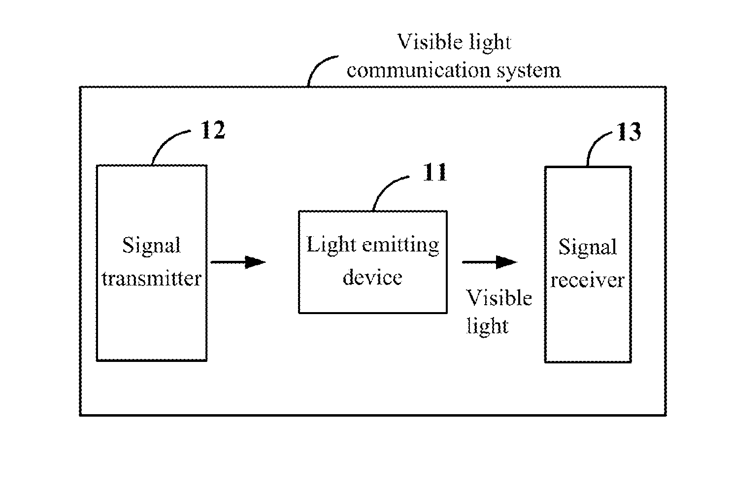
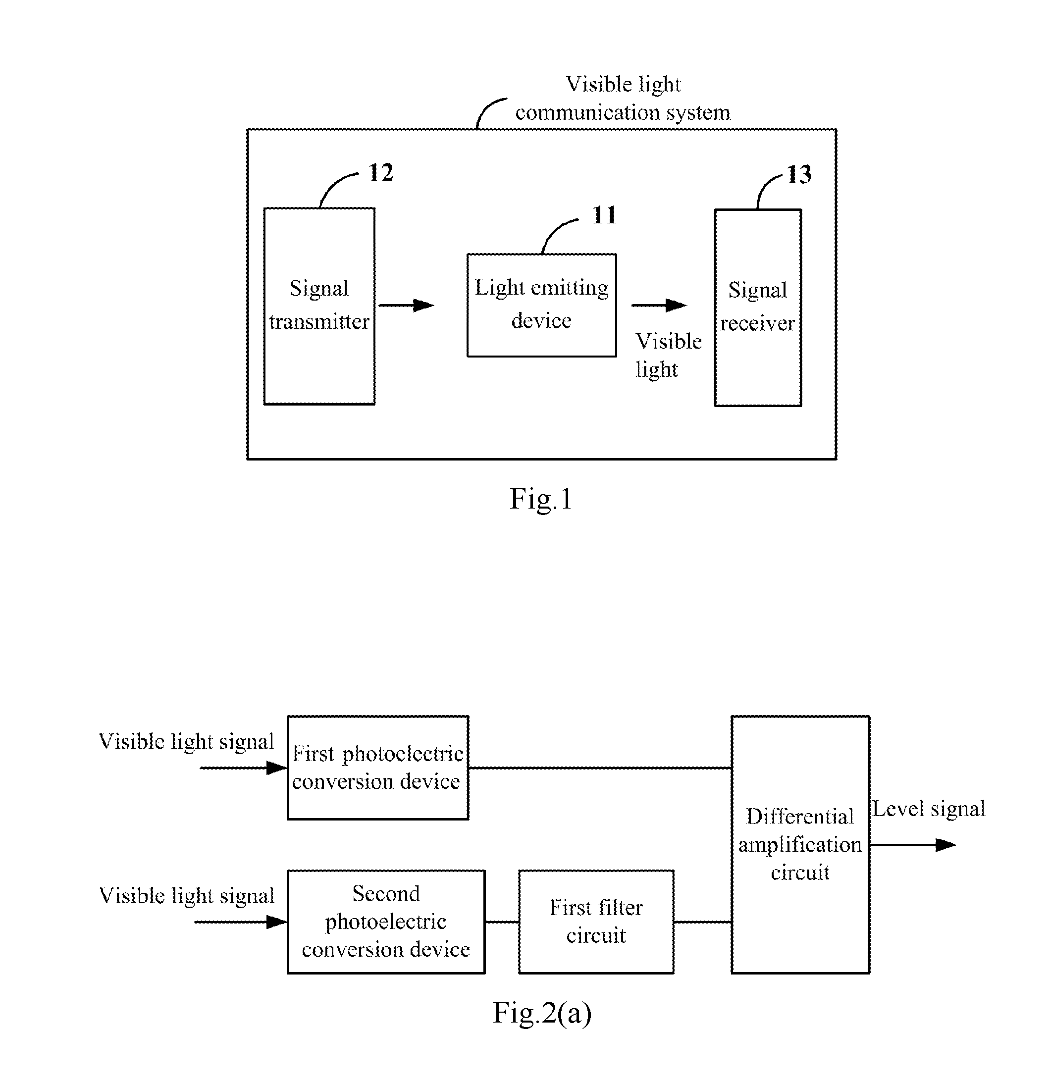
[0030]The first embodiment of the invention provides a visible light communication system, and as illustrated in FIG. 1 which is a possible schematic structural diagram of the visible light communication system according to the invention, where the visible light communication system can include a light emitting device 11, a signal transmitter 12, and a signal receiver 13, where:

[0031]The signal transmitter 12 can be configured to convert source signal data into a binary code stream, and to control the light emitting device 11 to be lightened or blacked out according to the binary code stream to create a visible light signal; and

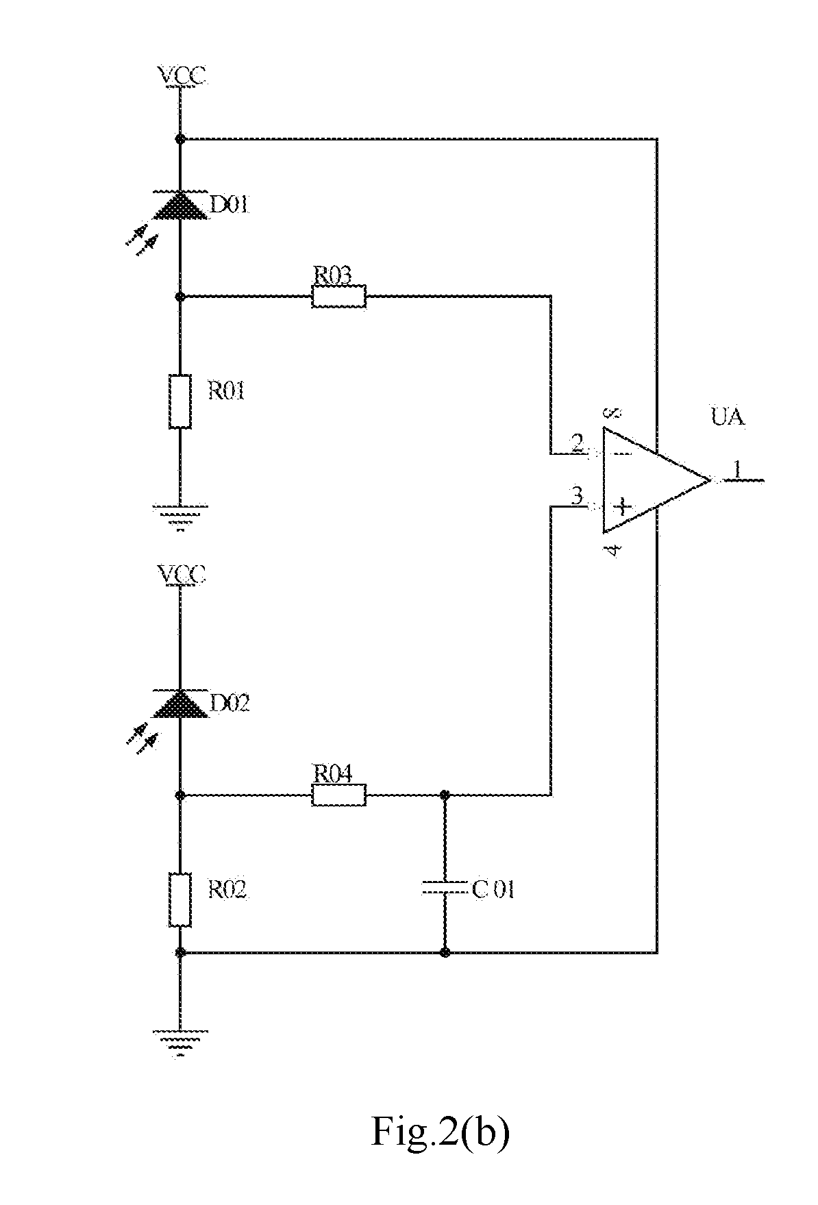
[0032]The signal receiver 13 can be configured to convert the visible light signal emitted by the light emitting device 11 into a first voltage amplitude signal, to perform a first filter process on the first voltage amplitude signal to obtain a second voltage amplitude signal in which the amplitude of the voltage signal around the frequency range of the visi...

second embodiment

[0088]Based upon the same inventive idea, a second embodiment of the invention provides a visible light communication method, and FIG. 6 illustrates a schematic flow chart of the visible light communication method according to the second embodiment of the invention, where the visible light communication method can include the following operations:

[0089]The operation 601 is to receive a visible light signal emitted by a light emitting device, and to convert the visible light signal into a first voltage amplitude signal, where as can be apparent from the related description in the first embodiment, the visible light signal can be created by a signal transmitter converting source signal data into a binary code stream, and controlling the light emitting device to be lightened or blacked out, according to the binary code stream.

[0090]The operation 602 is to perform a first filter process on the first voltage amplitude signal to obtain a second voltage amplitude signal in which the amplit...

third embodiment

[0100]Based upon the same inventive idea, a third embodiment of the invention provides a device for receiving a signal (i.e., the signal receiver), and reference can be made to the relevant description in the first and second embodiments for a particular implementation of the device for receiving a signal, so a repeated description thereof will be omitted here. FIG. 7 illustrates a schematic structural diagram of the device for receiving a signal according to the third embodiment of the invention, where the device for receiving a signal can include:

[0101]A signal converting unit 71 can be configured to receive a visible light signal emitted by a light emitting device, and to convert the visible light signal into a first voltage amplitude signal, where the visible light signal can be created by a signal transmitter converting source signal data into a binary code stream, and controlling the light emitting device to be lightened or blacked out, according to the binary code stream; and...


PUM


Abstract

The invention discloses a visible light communication system and method, and related devices, and in this solution, a visible light signal emitted by a light emitting device can be converted into a first voltage amplitude signal, a first filter process can be performed on the first voltage amplitude signal to obtain a second voltage amplitude signal in which the amplitude of the voltage signal around the frequency range of the visible light signal is suppressed, and the visible light signal can be converted into a level signal according to the voltage difference between the second voltage amplitude signal and the first voltage amplitude signal, to thereby address the problems of a required highly satisfactory light environment, low robustness to interference, a high bit error rate, etc., in visible light communication based upon constant reference voltage.

Description

CROSS-REFERENCE TO RELATED APPLICATIONS[0001]This application claims the benefit of Chinese Patent Application No. 201510350241.3, filed with the State Intellectual Property Office of People's Republic of China on Jun. 19, 2015, and entitled “Visible light communication system and method, and related device”, the content of which is hereby incorporated by reference in its entirety.TECHNICAL FIELD[0002]The present invention relates to the field of communications and particularly to a visible light communication system and method, and related device.BACKGROUND[0003]Visible light communication is a new short-distance wireless high-speed communication technology developed from Light Emitting Diode (LED) and other technologies, and operates under such a principle that a high-speed binary signal is emitted by a light source flickering at a high frequency because the LED or the like can be lighten or blacked out rapidly, and the binary signal is received and converted by a corresponding de...

Claims


Application Information

Patent Timeline
Patent Type & Authority Applications(United States)
IPC IPC(8): H04B10/116H04B10/66H04B10/50
CPCH04B10/116H04B10/66H04B10/502
Inventor ZOU, XIAO
Owner HANGZHOU SHINYEASY TECH CO LTD
Learn More