Seed sensor with lightpipe photodetect assembly

a technology of lightpipe and seed sensor, which is applied in the field of seed sensor with lightpipe photodetect assembly, can solve the problems of large dirt, dust, and interference with the proper operation of the photoresponsive system, and achieve the effects of improving performance, reducing seed spatial variability within the seed tube, and improving seed resolution

Active Publication Date: 2016-12-29
TSI INC
View PDF7 Cites 5 Cited by
  • Summary
  • Abstract
  • Description
  • Claims
  • Application Information

AI Technical Summary

Benefits of technology

[0007]In one example embodiment, a seed sensor was developed to fit the conventional mounting location on existing seed tubes but still provide improved performance over the current production sensors by providing a wide light source (more LEDS), a wide photodetector and a current profiling scheme for the LEDs that provides more light at the opposite ends of the LED array. A result of such an arrangement is to improve seed resolution and to reduce seed spatial variability within the seed tube.
[0008]In one example embodiment, a seed counting device is provided for counting seeds passing through a longitudinal portion of a seed tube having a front, back and two side walls, the counting device including a sensor assembly adapted to be mounted on a front and back wall of the seed tube, said sensor assembly including an LED (light emitting diode) array disposed opposite a photodetector device adapted to receive light from the LED array, the photodetector device configured to generate signal pulses in response to interruptions in light received from the LED array, the LED array comprised of a plurality of LEDs that are disposed in a line that is substantially perpendicular to the longitudinal portion of the seed tube. The seed counting device further includes a controller means configured to control a current driving each of the plurality of LEDs so as to generate a current profile for a selected LED array, controller means further configured to increase the drive current of at least one LED located adjacent to the tube side wall so as to increase its intensity, thereby improving spatial position detection of seed counting device of a seed passing through the seed tube and allow for adjustments to improve seed deposition accuracy.
[0009]In another example embodiment, a particle detection system is provided with improved spatial position detection for substantially distinguishing among particles such as seeds and dust, the particle counting system including a sensor assembly adapted to be mounted on opposite sides of a chute member through which the particles are to pass through, the sensor assembly including an LED (light emitting diode) array disposed on the chute member opposite a photodetector device adapted to receive light from the LED array, the photodetector device configured to generate signal pulses in response to interruptions in light received from the LED array, the LED array comprised of a plurality of LEDs that are disposed in a line that is substantially perpendicular to the longitudinal axis of the chute member. The particle detection system also including a controller means configured to control a current driving each of the plurality of LEDs so as to generate a current profile for a selected LED array, controller means further configured to increase the drive current of at least two LEDs located at each end of the LED array so as to increase its intensity, thereby improving spatial position detection of the particle passing through the chute member and allow for adjustments to improve particle deposition accuracy. In a related embodiment, wherein controller means is configured to individually pulse the LEDs in the array so as to improve particle detection and deposition. In another related embodiment, controller means is configured to communicate with a particle deposition system so as to modify a ground speed of the deposition system as a function of a particle detection data received by controller means.

Problems solved by technology

However, various challenges to accuracy of seed counting are encountered including considerable dirt, dust and the like as the planter moves through the field.
Accordingly, the foregoing accumulations of material in the seed tube tend to interfere with proper operation of the photoresponsive system.
These changes may, if uncompensated for, greatly reduce the reliability of the response of the photoresponsive element.
A related problem is that of drift or changes over time in the nominal characteristics of the circuit elements utilized in the electronic circuits.
Such drift may occur for example due to environmental changes, detracting from optimum operation of the circuits and hence from the reliability of the count obtained therefrom.
Yet another challenge occurs as seed deposition rates increase the ability to reliably count multiple seeds which fall through the seed chute in close proximity or even partially overlapping decrease.
In such instances, both the photoresponsive element and the associated electronic circuit may be unable to respond rapidly enough to reliably produce a separate counting pulse for each seed.
A related problem is often encountered with relatively small, fast moving seeds such as soybeans.
Hence, today's seed sensing systems may be incapable of sufficiently rapid response to reliably count each seed and to distinguish between seeds and dust or other foreign matter.

Method used


Image

  • Seed sensor with lightpipe photodetect assembly
  • Seed sensor with lightpipe photodetect assembly
  • Seed sensor with lightpipe photodetect assembly

Examples


Embodiment Construction

[0025]Following are more detailed descriptions of various related concepts related to, and embodiments of, methods and apparatus according to the present disclosure. It should be appreciated that various aspects of the subject matter introduced above and discussed in greater detail below may be implemented in any of numerous ways, as the subject matter is not limited to any particular manner of implementation. Examples of specific implementations and applications are provided primarily for illustrative purposes.

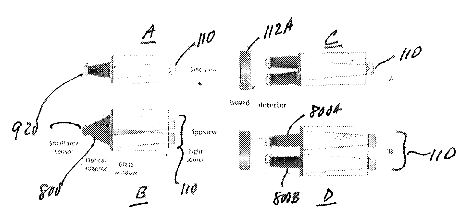
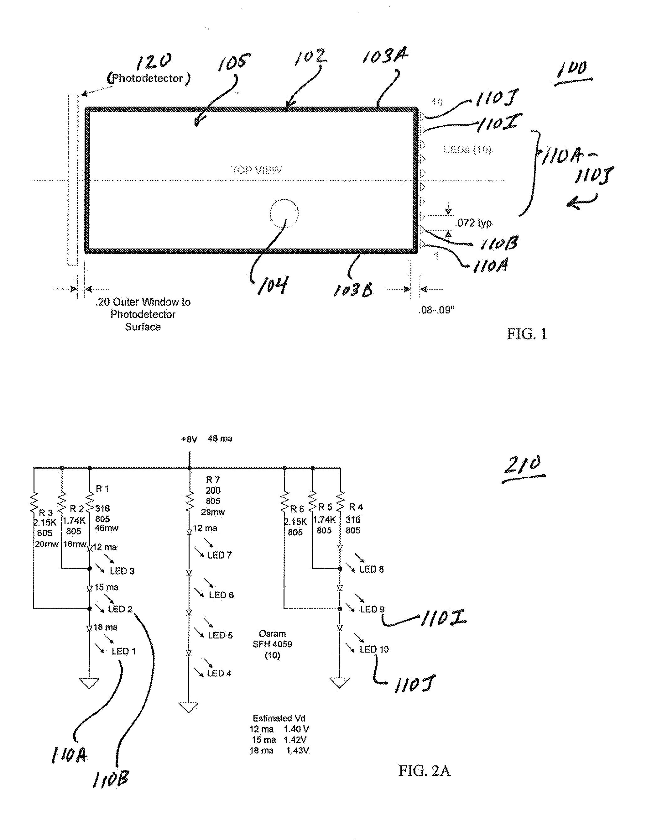
[0026]Referring now to FIG. 1, there is shown one example embodiment of a seed sensor assembly 100 in a seed tube 102. Specifically, there is shown a top, cutaway view of seed tube 102 with a seed 104 dropping through the tube with a 10 LED array 110A-110J on one end and a photodetector member 120 on the other (in this example embodiment there is also a clear window in front of the photodetector). This figure shows a top view of seed tube 102 with one seed 104 free-falling. B...


PUM


Abstract

In one example embodiment, a seed sensor is disclosed adapted to fit a conventional mounting location in existing seed tubes that provides improved performance by providing a wide light source (more LEDS), a wide photodetector and a current profiling scheme for the LEDs that provides more light at the opposite ends of the LED array. A result of such an arrangement is to improve seed resolution and to reduce seed spatial variability within the seed tube.

Description

CLAIM OF PRIORITY[0001]This application claims priority to and the benefit of the following provisional patent applications having Ser. No. 61 / 693,573 and filed on Aug. 27, 2012, and Ser. No. 61 / 698,163 Sep. 7, 2012, respectively, which are hereby incorporated by reference in their entireties.BACKGROUND[0002]As is known in the art, a field seed planter includes a group of seed chutes or seed discharge tubes, one for each row for simultaneous planting. Each of these seed chutes or tubes convey individual seeds from a seed dispenser in conjunction with a hopper or other seed supply to individual furrows formed in the ground by the planter as it moves across a field. Various monitoring and counting arrangements have been utilized for obtaining a count of the number of seeds dispensed by such seed planters. Such counting is particularly useful in determining and controlling the density or population of seeds planted in order to optimize crop yield. Also, more recently, seed spacing info...

Claims


Application Information

Patent Timeline
Patent Type & Authority Applications(United States)
IPC IPC(8): A01C7/10G01B11/14A01C7/20
CPCA01C7/105G01B11/14A01C7/206
Inventor STEFFEN, RONALD W.QI, DAHUMILLER, GREGRY C.
Owner TSI INC
Why Eureka
Try Eureka