Time of flight camera for welding machine vision

a technology of welding machine and time flight camera, which is applied in the direction of manufacturing tools, soldering devices, auxillary welding devices, etc., can solve the problems of high cost, limited field of view, and difficulty in identifying the welding operator

Active Publication Date: 2016-12-29
ILLINOIS TOOL WORKS INC
View PDF7 Cites 42 Cited by
  • Summary
  • Abstract
  • Description
  • Claims
  • Application Information

AI Technical Summary

Benefits of technology

[0003]Methods and systems are provided for time of flight camera for welding machine vision, substantially as illustrated by and / or described in connection with at least one of the figures, as set forth more completely in the claims.

Problems solved by technology

Weld operators and welding robot equipped with conventional optical cameras suffer from obscured vision in a harsh arc welding environment.
The problem is compounded with excessive fume and spatter conditions of certain wire, gas and welding processes.
Laser scanners overcome the arc brightness and fume obstruction but suffer from high cost and limited field of view, and are typically used for seam finding and tracking applications.

Method used


Image

  • Time of flight camera for welding machine vision
  • Time of flight camera for welding machine vision
  • Time of flight camera for welding machine vision

Examples


Embodiment Construction

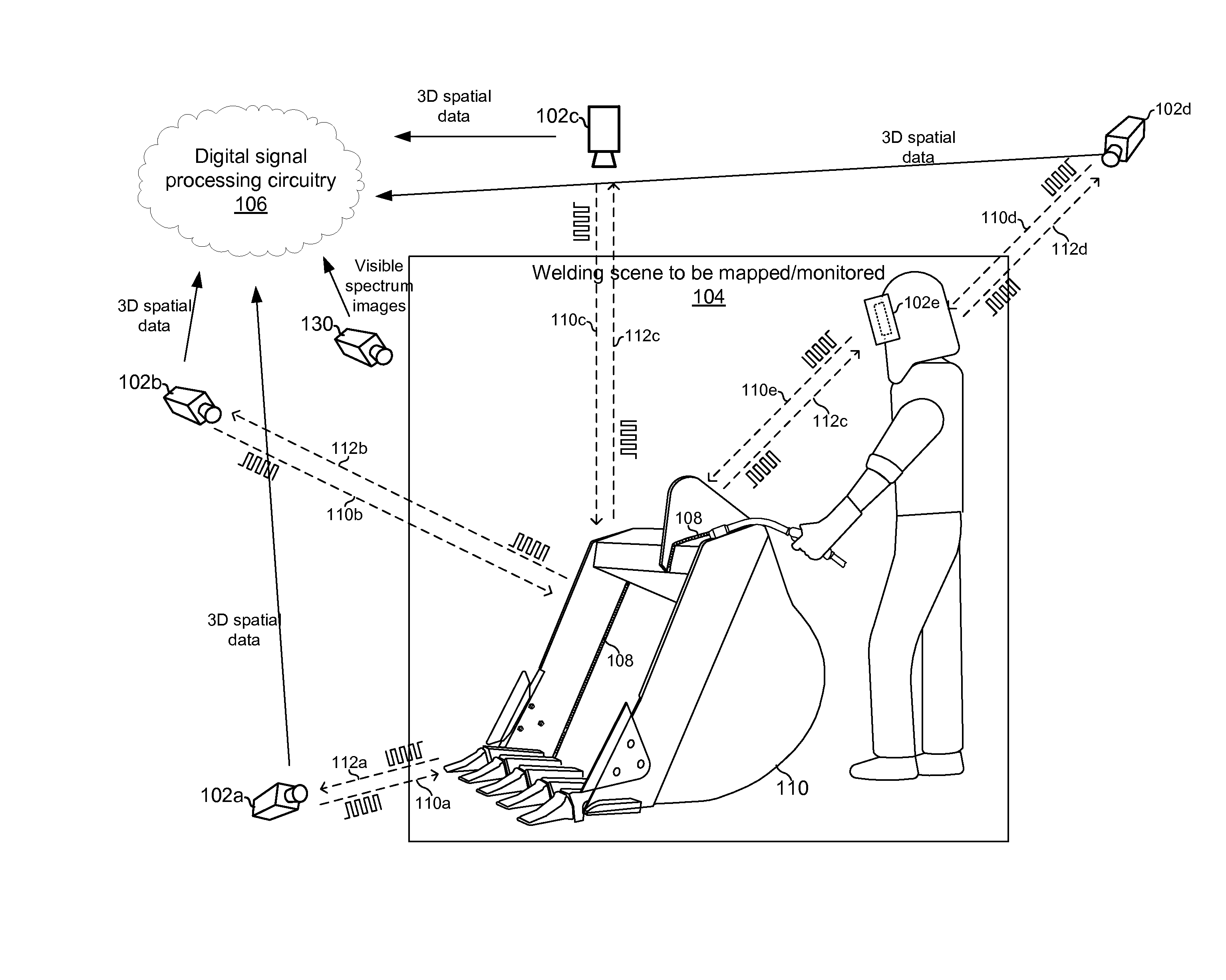
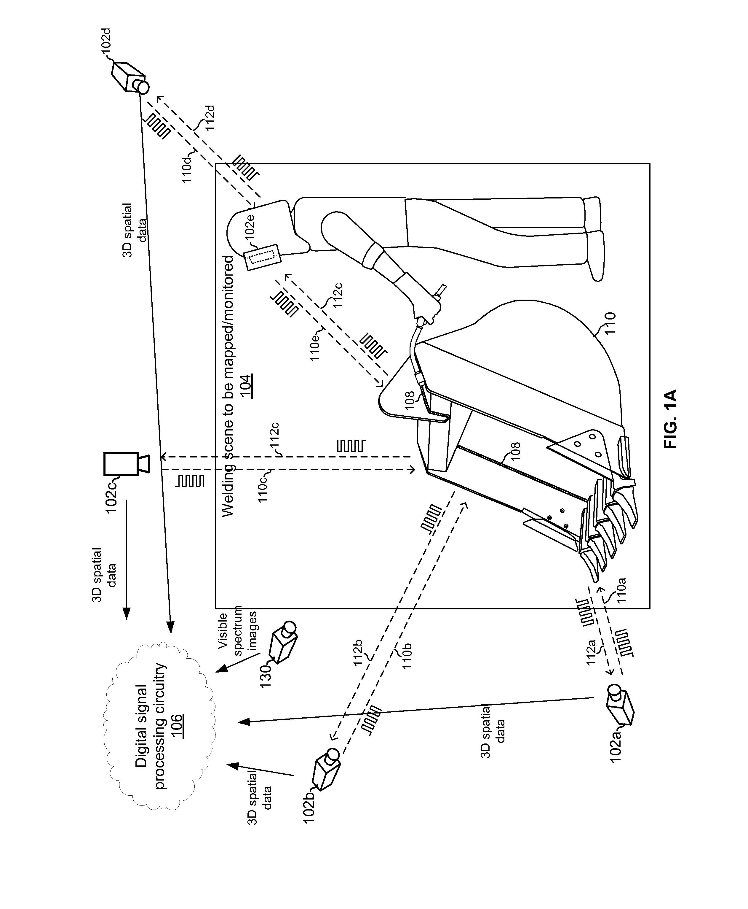
[0013]FIG. 1A illustrates monitoring of a fabrication work cell (including welding, and pre-welding and post-welding activities, and other non-welding fabrication activities such as cutting, heating, brazing, induction heating, soldering, and / or the like) scene using time-of-flight (ToF) imaging. Shown are a plurality of ToF cameras 102a-102d monitoring a welding scene from a variety of distances and angles. The ToF cameras 102a-102d generate 3D spatial data (e.g., “point clouds”) and convey that data via wired and / or wireless network to digital signal processing circuitry 106. The welding system 106 comprises welding equipment which may include, for example, a welding power source, a welding wire feeder, a welding gas flow regulator, a welding torch, a welding fixture for positioning workpieces to be welded, an automated welding robot, welding wearables (e.g., electronic headwear, wristbands, packs, etc.), a computer workstation for monitoring a welding process, a computer system f...


PUM

PropertyMeasurementUnit
wavelengthaaaaaaaaaa

Abstract

A machine-vision-assisted welding system comprises welding equipment, a time of Flight (ToF) camera operable to generate a three-dimensional depth map of a welding scene, digital image processing circuitry operable to extract welding information from the 3D depth map, and circuitry operable to control a function of the welding equipment based on the extracted welding information. The welding equipment may comprise, for example, arc welding equipment that forms an arc during a welding operation, and a light source of the ToF camera may emit light whose spectrum comprises a peak that is centered at a first wavelength, wherein the first wavelength is selected such that a power of the peak is at least a threshold amount above a power of light from the arc at the first wavelength.

Description

BACKGROUND[0001]Weld operators and welding robot equipped with conventional optical cameras suffer from obscured vision in a harsh arc welding environment. The sharp light intensity contrast of welding arc and surroundings make it difficult to see the seam, electrode placement within the seam, torch and travel angles, liquid weld puddle shape and position, and finished weld size and position with good clarity. The problem is compounded with excessive fume and spatter conditions of certain wire, gas and welding processes.[0002]Laser scanners overcome the arc brightness and fume obstruction but suffer from high cost and limited field of view, and are typically used for seam finding and tracking applications.BRIEF SUMMARY[0003]Methods and systems are provided for time of flight camera for welding machine vision, substantially as illustrated by and / or described in connection with at least one of the figures, as set forth more completely in the claims.BRIEF DESCRIPTION OF THE DRAWINGS[00...

Claims


Application Information

Patent Timeline
Patent Type & Authority Applications(United States)
IPC IPC(8): B23K31/02B23K37/00
CPCB23K37/00B23K31/02B23K9/095B23K9/32A61F9/06B23K9/127B23K26/03B23K26/044
Inventor HSU, CHRISTOPHER
Owner ILLINOIS TOOL WORKS INC
Why Eureka
Try Eureka