Multihull Watercraft

a multi-hull, watercraft technology, applied in the direction of special-purpose vessels, marine propulsion, vessel construction, etc., can solve the problems of narrow monohull, narrow hull, lateral stability, and a greater risk of capsize, so as to improve interior ventilation, improve thermal isolation, and improve the effect of interior ventilation

Active Publication Date: 2016-12-29
SALANI STEVEN JOHN
View PDF2 Cites 6 Cited by
  • Summary
  • Abstract
  • Description
  • Claims
  • Application Information

AI Technical Summary

Benefits of technology

[0009]Unlike conventional multihulls that use the cramped float hulls for accommodation, the present invention moves the passenger cabins to the upper hull several feet above the water-line. This removes the conflict between the accommodation space and the float hull form; each can be independently optimized without compromising the other. The higher elevation improves interior ventilation, increases thermal isolation between the cabins and the water, and provides better view of the surroundings for both skipper and passengers.
[0010]There are four support structures between the upper hull and the float hulls which are designed to reduce windage from the high cross winds that can be encountered at sea. Each structure is comprised of a plurality of narrow columns that provide mechanical support while allowing lateral air flow.
[0011]In order to maximize the accommodation space, the forward and aft portions of the upper hull (enclosing the private cabins) extend laterally over the left and right float hulls. The central portion (enclosing the salon, galley, and other common areas) of the main hull is narrower, extending laterally to points inboard of the longitudinal centerline of the left and right float hulls. This unique configuration creates space for deck areas on the top side of the left and right float hulls. The low freeboard of the twin decks allow easy boarding and disembarking to docks on either side of the boat, and safer boarding of shore craft.
[0012]Access to the upper hull is via a staircase from the deck of the left or right float hull. This eliminates the need for portable boarding stairs at the dock; passengers simply step onto the deck of the float hull, then go up the stairs into the upper hull.
[0013]The present invention offers an improved method of storing and deploying a shore craft (dinghy). When not in use, the dinghy is stored in a compartment located on the underside of the upper hull. To launch the dinghy, the compartment cover is lowered to provide access to the compartment via the adjacent float hull deck. The dinghy is moved across the deck and into the water along the outside edge of the hull where it can be easily and safely boarded. In an alternate embodiment, the dinghy may be lowered directly into the water, where it may be boarded from the inboard edge of the adjacent float hull deck.
[0014]The present invention incorporates a new sail configuration that is substantially easier to operate and maintain in comparison to the typical Bermuda rig found on most sailboats. The rig includes a forward sail and an aft sail which can be rotated simultaneously to the optimum position for the current wind direction. The rotation of the rig can be set by manually turning a single winch, control wheel, or equivalent electrical means.

Problems solved by technology

One big disadvantage of a narrow monohull is lateral stability.
The narrow hull presents a greater risk of capsize, especially for sailboats.
Making the boat wider increases the stability, but creates much more drag though the water.
The heavy ballast adds stability, but the boat is pulled deeper into the water which increases the water displacement and again increases drag.
As the multihull form developed into the 21st century, it continued to offer many advantages over traditional monohulls, but the design still has several inherent problems.
There is a conflict between accommodation space and hull form.
The narrow shape of catamaran and trimaran hulls, while highly efficient when moving through the water, also create awkward interior spaces.
Widening the hull improves the accommodation space but seriously de-grades the performance of the boat.
Conventional multihulls have a further problem of awkward boarding and disembarking.
The high freeboard also results in high amounts of lateral windage.
Compensating for this windage while under way wastes a significant amount of energy, and docking and maneuvering in a tight marina can be difficult as the wind pushes the boat off course.
Conventional multihulls have a further problem of awkward storage and deployment of a shore craft (dinghy).
Storage on deck takes up valuable space and may also require a crane for deployment.
Dinghy davits (typically a pair of metal arms used for both storage and deployment) are also not an optimum solution in terms of convenience and aesthetic appeal.
In either case, boarding and exiting the dinghy can be awkward and dangerous because there is no suitable boarding platform.
Conventional multihulls have a further problem of very complicated sailing rigs.
The standard Bermuda rig is difficult to operate and maintain.
The sheer number of mechanical components also makes the system prone to failure.

Method used


Image

  • Multihull Watercraft
  • Multihull Watercraft
  • Multihull Watercraft

Examples


Embodiment Construction

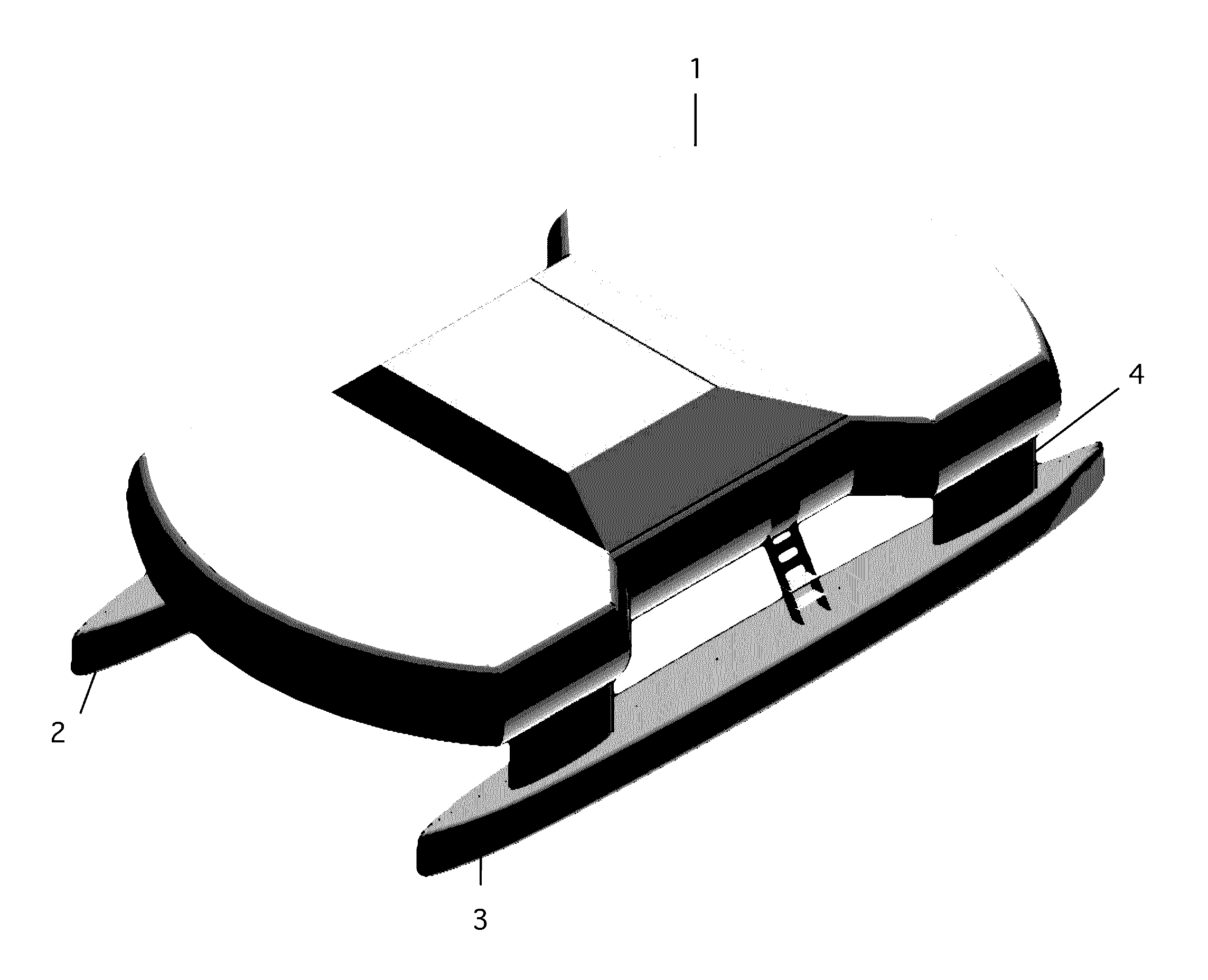
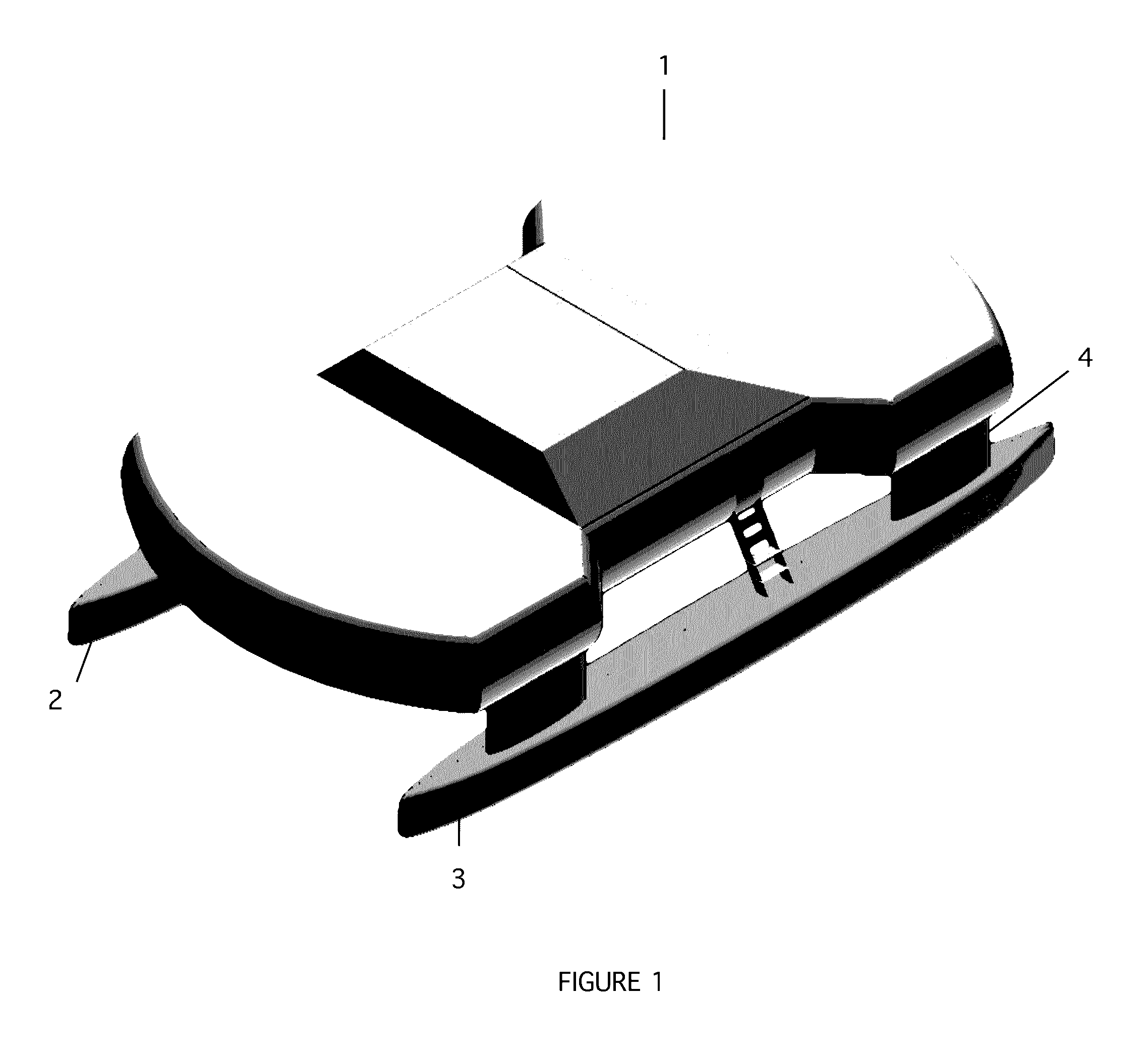
[0027]FIG. 1 illustrates an embodiment of the present invention in a powerboat configuration (without sails). A large upper hull 1 is suspended over a left float hull 2 and right float hull 3 by means of four support structures 4. The wide support structures shown in FIG. 1 may be improved by utilizing two or more narrow beams per support structure, which allows lateral air flow and thereby reduces lateral windage. The improved support structure 4 is shown in FIG. 2.

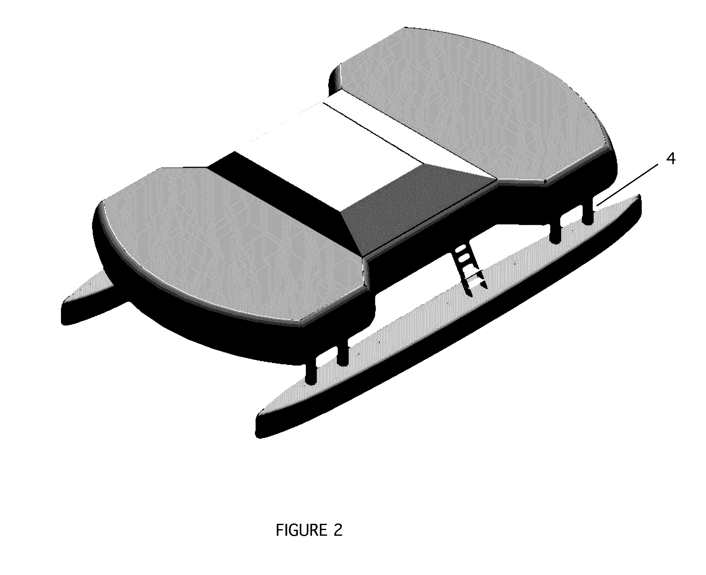
[0028]The top-view diagram in FIG. 3 illustrates the relative width of the upper hull 1 in comparison to the twin float hulls 2 and 3. The forward and aft portions of the upper hull enclose the passenger cabins, and extend laterally beyond the longitudinal centerline of the left and right float hulls to maximize the accommodation space. The middle portion of the upper hull encloses the common areas (salon, galley, storage, etc), and is constrained to the region inboard of the longitudinal centerline of the left and right...


PUM


Abstract

The patent discloses a multihull watercraft with a unique hull configuration providing numerous benefits. By relocating the passenger cabins from the float hulls to the upper hull, the accommodation space and the float hulls may be independently optimized. The new configuration also provides reduced windage, and creates additional deck space for easier boarding, recreational use, and safer access to shore craft. A new sailing rig is also disclosed that is easier to operate and maintain than the conventional Bermuda rig. The entire rig can be rotated with a single winch or control wheel to achieve the optimum angle of attack into the wind.

Description

BACKGROUND OF THE INVENTION[0001]The modern monohull watercraft can be traced back to the hollowed log canoes used by primitive cultures around the world. The long narrow hull of these ancient boats is a very efficient shape in the water, which is an important feature for a vehicle propelled only by human or wind power. In today's world of limited resources and energy an efficient hull shape continues to be a very desirable feature. For a given displacement, a hull with high aspect ratio (the length divided by the width) is much easier to push through the water than a hull with low aspect ratio.[0002]One big disadvantage of a narrow monohull is lateral stability. The narrow hull presents a greater risk of capsize, especially for sailboats. Making the boat wider increases the stability, but creates much more drag though the water. An alternate solution is to keep the narrow hull form, but add ballast in the form of a weighted keel. The heavy ballast adds stability, but the boat is pu...

Claims


Application Information

Patent Timeline
Patent Type & Authority Applications(United States)
IPC IPC(8): B63H9/08B63B3/38B63B29/02
CPCB63H9/08B63B29/02B63H2009/086B63B2003/145B63B2001/204B63B3/38B63B1/121B63B1/10B63B15/0083B63B23/02B63B27/36B63B29/00B63B2035/004B63B2035/009B63H9/1021B63H2009/088
Inventor SALANI, STEVEN JOHN
Owner SALANI STEVEN JOHN
Why Eureka
Try Eureka