
Separator for nonaqueous electrolyte secondary battery, and battery including same

a nonaqueous electrolyte and separator technology, applied in the direction of cell components, cell component details, transportation and packaging, etc., can solve the problems of affecting the function of separators holding nonaqueous electrolyte (liquid retention characteristic), deteriorating cycle characteristics, and reducing battery resistance. , the effect of reducing the generation of micro short-circuits

Active Publication Date: 2016-12-29
TOYOTA JIDOSHA KK
View PDF0 Cites 9 Cited by
  • Summary
  • Abstract
  • Description
  • Claims
  • Application Information

AI Technical Summary

Benefits of technology

The invention introduces a separator that is resistant to crushing under strong stress, and a nonaqueous electrolyte secondary battery that utilizes this separator.

Problems solved by technology

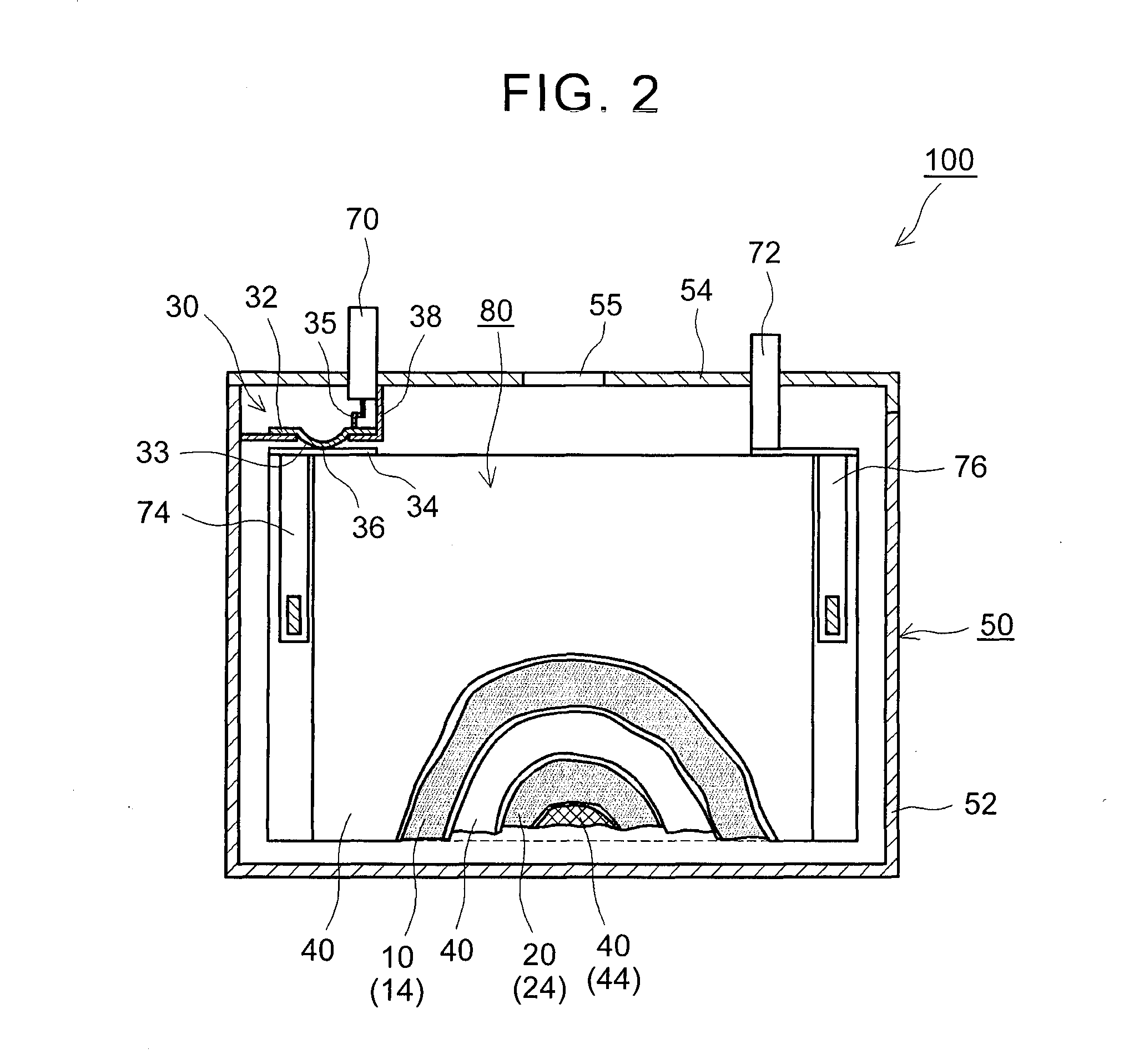
However, in the aforementioned battery, there is a possibility that the cycle characteristic is deteriorated or the operation of a current interrupt device (CID) when overcharged is delayed.
In this case, the separator's function of holding a nonaqueous electrolyte (liquid retention characteristic) may be impaired.

Method used


Image

  • Separator for nonaqueous electrolyte secondary battery, and battery including same
  • Separator for nonaqueous electrolyte secondary battery, and battery including same
  • Separator for nonaqueous electrolyte secondary battery, and battery including same

Examples


example 1

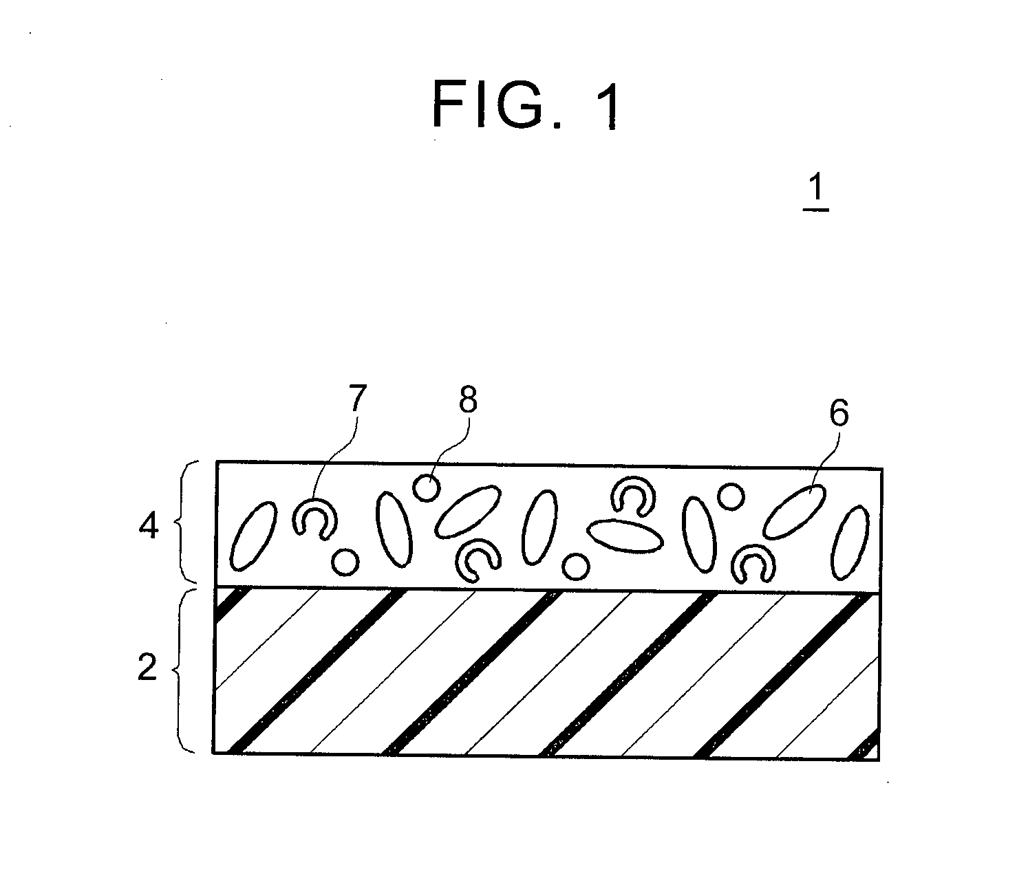
[0057]First, alumina powder (having an average particle diameter of 0.5 μm and a BET specific surface area of 4 m2 / g) as an inorganic filler, hollow bodies made of an acryl resin, and styrene-butadiene rubber (SBR) as a binder were weighed at amass ratio of 85:10:5, and were mixed with ion-exchanged water using CLEARMIX (registered trademark) made by M Technique Co., Ltd., thereby producing a slurry composition. The composition was gravure-coated on one surface of a separator substrate having a three-layer structure of PP / PE / PP (having an average thickness of 20 μm and a porosity of 70 volume %) and was dried, thereby producing a separator sheet (having a total thickness of 25 μm) which includes a porous heat resistance layer having an average thickness of 5 μm formed on one surface of the substrate.

[0058]Then, a slurry composition was produced by mixing LiNi1 / 3Co1 / 3Mn1 / 3O2 powder as a positive electrode active material, polyvinylidene fluoride (PVdF) as a binder and acetylene black...

examples 2 to 14

[0061]In each of examples 2 to 14, 55 (N=55) nonaqueous electrolyte secondary batteries were produced in the same manner as in example 1 described above except that the properties (the particle porosity and the average particle diameter) of the hollow bodies and the content percentage of the hollow bodies in the porous heat resistance layer are changed as shown in Table 1 below. In examples 6, 7, 13 and 14 in which the content percentages of the hollow bodies in the porous heat resistance layers are differently set from the others, the difference of the hollow bodies from the whole solid content was allocated to the inorganic filler and the binder at the same percentage as in example 1.

TABLE 1High TemperatureCycle CharacteristicStorage(50° C.,Characteristic (60° C.)1000 cycles)OverchargeHollow BodiesInitialSeparatorTest afterAveragePropertyCapacityThicknessCapacityHighParticleParticleContentIVRetentionafterRetentionTemperaturePorositydiameterPercentageResistanceRateCycleRateStorage(...


PUM

PropertyMeasurementUnit
particle porosityaaaaaaaaaa
particle diameteraaaaaaaaaa

Abstract

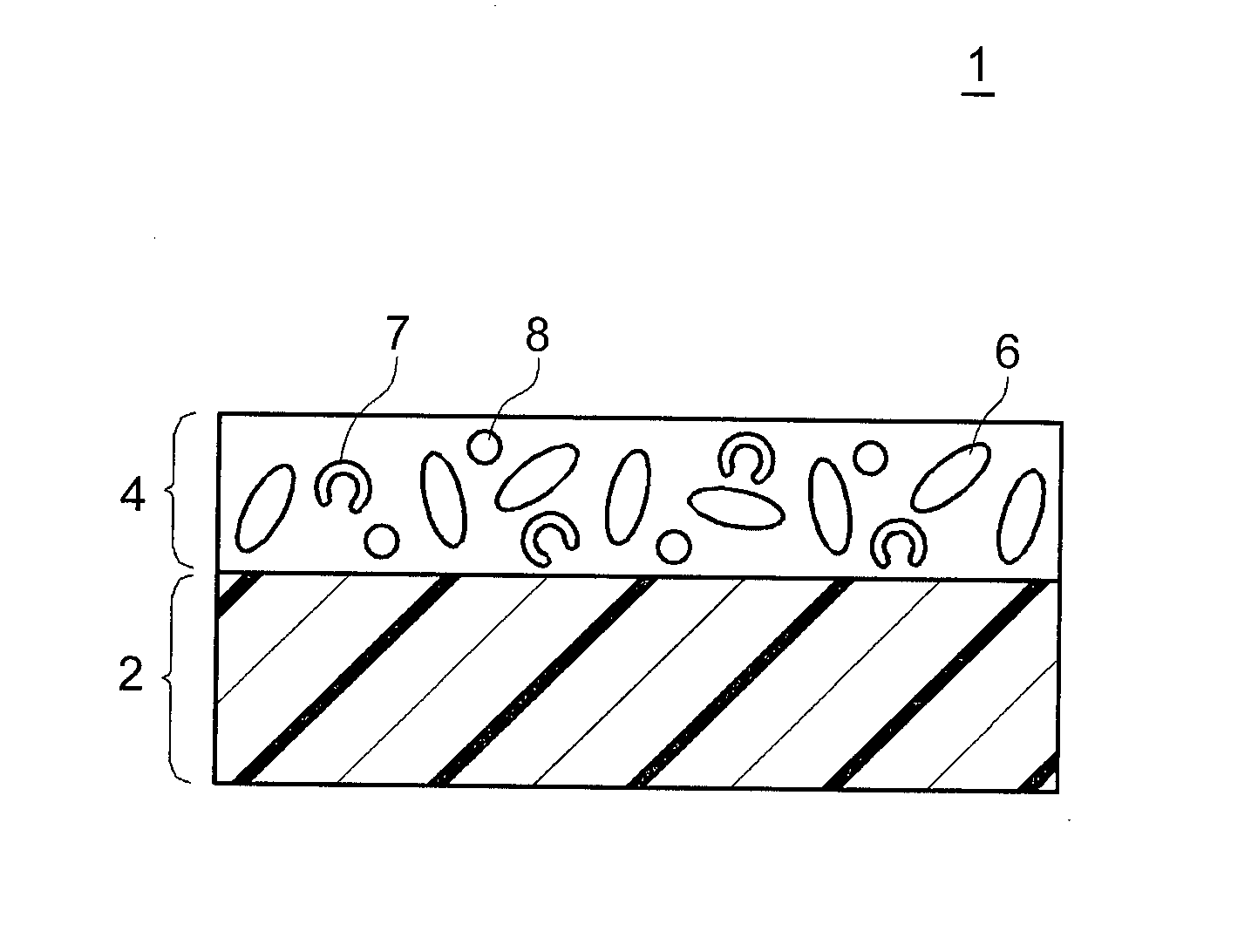
A separator 1 for a nonaqueous electrolyte secondary battery, includes a resin-made substrate (2) and a porous heat resistance layer (4) disposed on the substrate. The porous heat resistance layer includes an inorganic filler (6) and hollow bodies (7). The hollow body includes a shell portion and a hollow portion. The shell portion is formed of an acryl resin. The hollow portion is formed inside the shell portion. An opening portion extending through the shell portion to spatially interconnect the hollow portion and the outside of the shell portion is formed in the shell portion.

Description

BACKGROUND OF THE INVENTION[0001]1. Field of the Invention[0002]The present invention relates to a separator for a nonaqueous electrolyte secondary battery and a battery including the same. More particularly, the present invention relates to a separator which includes a resin-made substrate and a porous heat resistance layer disposed on the substrate.[0003]2. Description of Related Art[0004]A nonaqueous electrolyte secondary battery such as a lithium-ion secondary battery, a nickel-hydrogen battery or the like is extensively used as a so-called portable power supply or as a power supply for driving a motor vehicle. In particular, a lithium-ion secondary battery, which is light in weight and which is capable of obtaining a high energy density, is desirably used as a high-output power supply for driving a motor vehicle such as an electric vehicle, a hybrid vehicle or the like. In general, the nonaqueous electrolyte secondary battery of this kind includes a positive electrode, a negati...

Claims


Application Information

Patent Timeline
Patent Type & Authority Applications(United States)
IPC IPC(8): H01M2/16H01M50/414H01M50/429H01M50/449H01M50/454H01M50/457H01M50/491
CPCH01M2/166H01M2/1686H01M10/052Y02E60/10H01M50/446H01M50/449H01M50/429H01M50/491H01M50/454H01M50/414H01M50/457Y02T10/70H01M50/443H01M50/463
Inventor UMEYAMA, HIROYAHASHIMOTO, TATSUYAFUKUMOTO, YUSUKEOHARA, KEISUKETORIYAMA, KOUICHI
Owner TOYOTA JIDOSHA KK
Learn More