Particle beam treatment system with solenoid magnets

a treatment system and solenoid magnet technology, applied in the field of particle beam treatment system, can solve the problems of occupying a comparatively large amount of space in the system as a whole, requiring a comparatively large amount of space in the beam guidance system and the switches provided therein, and achieving the effect of improving beam properties and requiring little additional spa

Inactive Publication Date: 2017-01-12
CRYOELECTRA
View PDF3 Cites 9 Cited by
  • Summary
  • Abstract
  • Description
  • Claims
  • Application Information

AI Technical Summary

Benefits of technology

[0092]This allows the beam properties to be improved while taking up little additional space. As a result of the collimator unit, the phase space of the beam of charged particles of the beam further transported behind the collimator unit can be restricted.
[0093]The collimator unit is, for example, designed as a scre...

Problems solved by technology

The prior art particle beam treatment systems, that is to say the systems as a whole and in particular the beam guidance systems, however, take up a comparatively large amount of space.
But, this is only possible where several treatment locations are provided for and a lot of space is available any way.
In addition, the beam guidance sy...

Method used


Image

  • Particle beam treatment system with solenoid magnets
  • Particle beam treatment system with solenoid magnets
  • Particle beam treatment system with solenoid magnets

Examples


Embodiment Construction

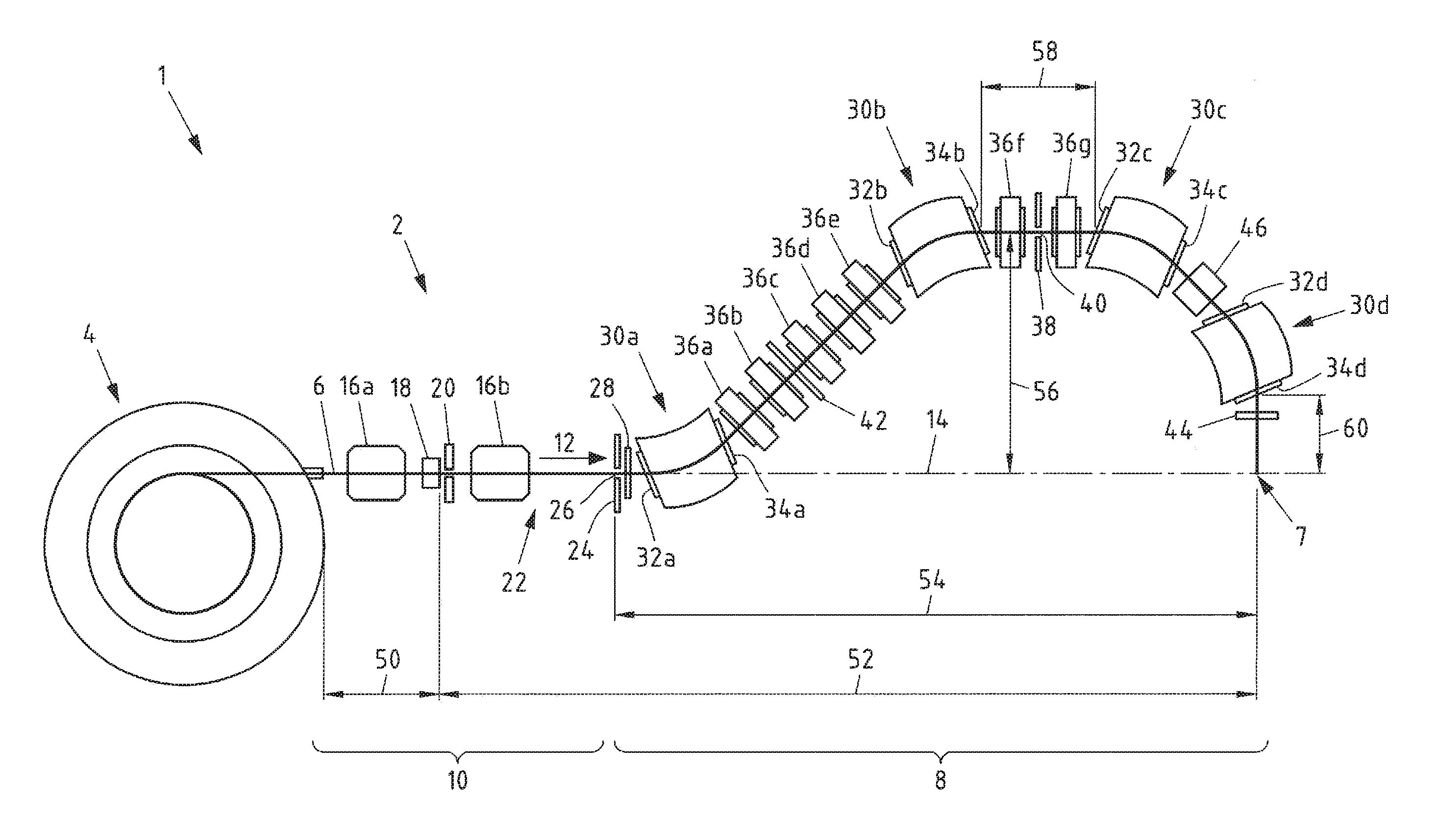
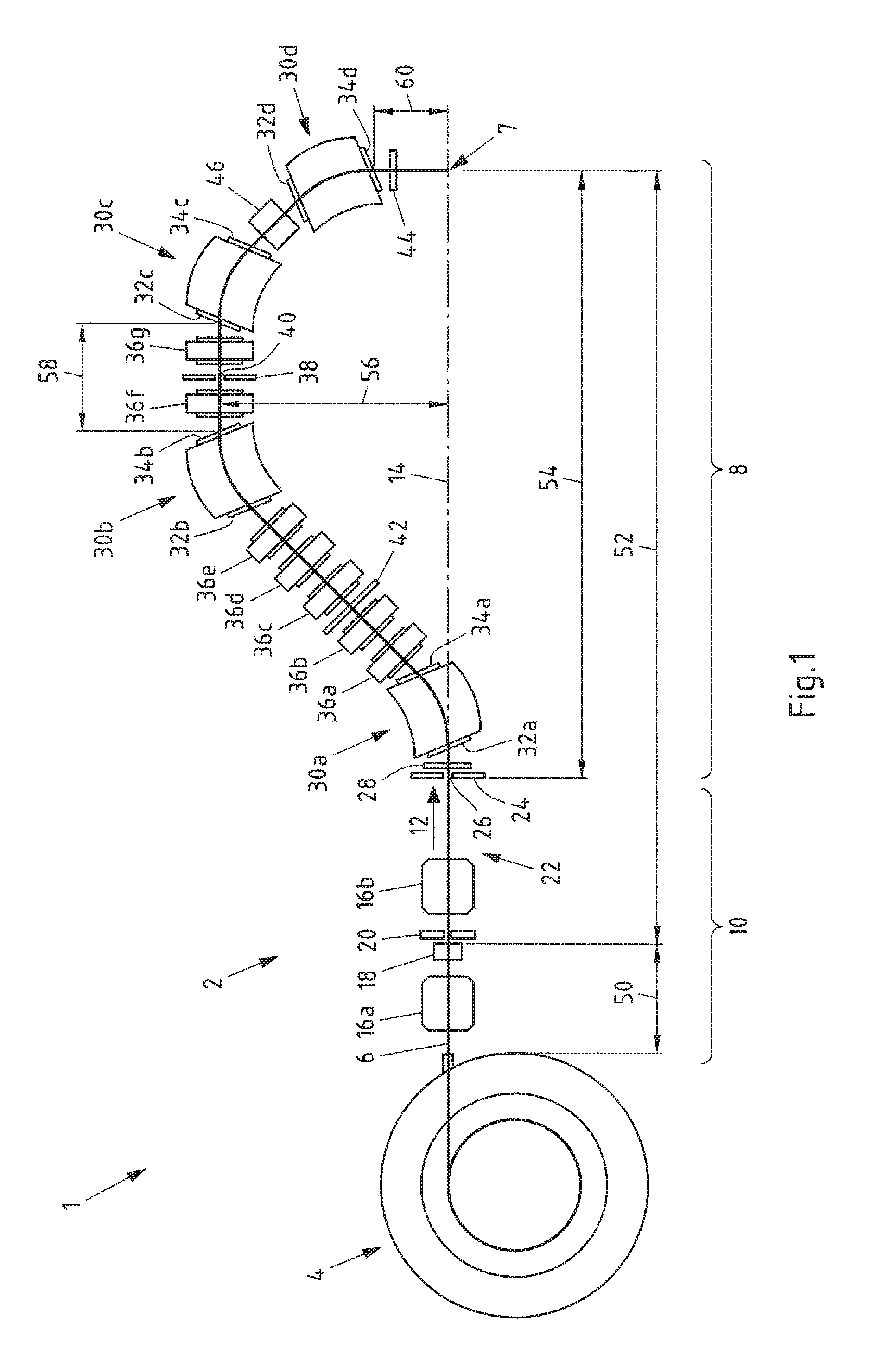
[0109]FIG. 1 shows a schematic sectional view of an embodiment of a particle beam treatment system 1 with an embodiment of a beam guidance systems 2. The particle beam treatment system comprises a beam generation unit 4 for generating a beam of charged particles 6, which in particular can be protons. The beam of charged particles 6 is guided by the beam guidance system 2 to a treatment site 7. The beam guidance system 2 has a section 8 that is moveable, in this case rotatable through 360°, and a section 10 that is immovable. The rotatable section 8 can for example be built as a supporting frame in the form of a gantry (not shown).

[0110]The beam generation unit 4 is in this case a cyclotron, that is to say an accelerator device which generates the beam of charged particles 6 with constant energy. The beam generation unit 4 emits charged particles with a constant kinetic energy, for example 210 MeV, 215 MeV or 250 MeV. It has been shown that by means of charged particles with a kineti...


PUM


Abstract

A particle beam treatment system having a beam generation unit for generating a beam of charged particles, in particular ions, preferably protons, and having a beam guidance system. The generic beam guidance system takes up less space but can provide comparable or even improved beam properties because, in part, the beam guidance system seen in the direction of the beam of charged particles and behind the beam generation unit has at least one solenoid magnet as a beam shaping unit, and the at least one solenoid magnet of the beam guidance system is a superconducting solenoid magnet.

Description

CROSS-REFERENCE TO RELATED PATENT APPLICATION[0001]This patent application claims priority to German Application No. 10 2015 111 060.1, filed Jul. 8, 2015, the entire teachings and disclosure of which are incorporated herein by reference thereto.FIELD OF THE INVENTION[0002]According to a first aspect, the invention concerns a particle beam treatment system with a beam generation unit for generating a beam of charged particles, in particular ions, preferably protons, and with a beam guidance system. According to a second aspect, the invention also concerns an advantageous method.BACKGROUND OF THE INVENTION[0003]In the state of the art, the abovementioned particle beam treatment systems are used for radiotherapy with charged particles, for example ions in the form of protons. Compared with the hitherto usual radiotherapy with ion, in particular photons there are considerable advantages for patients with certain cancers. Irradiation with protons is particularly advantageous, because th...

Claims


Application Information

Patent Timeline
IPC IPC(8): A61N5/10H01J37/147H01J37/14
CPCA61N5/10H01J37/14H01J2237/152A61N2005/1087H01J2237/141H01J37/1472G21K1/093A61N2005/1095G21K1/10G21K5/04
Inventor DREES, JURGENPIEL, HELMUT
Owner CRYOELECTRA
Why Eureka
Try Eureka