
Ultrasonic medical probe with failsafe for sterility and associated method

a technology of ultrasonic medical probes and failsafes, applied in the field of ultrasonic medical tools or probes, can solve the problems of inoperable probes, weakening of prospective users or re-users, and probes that snap or bend at the recesses, and achieve optimal structural and operational characteristics, optimal tool efficacy, and the effect of optimal structural characteristics

Active Publication Date: 2017-01-12
MISONIX INC
View PDF2 Cites 10 Cited by
  • Summary
  • Abstract
  • Description
  • Claims
  • Application Information

AI Technical Summary

Benefits of technology

The present invention aims to provide an ultrasonic medical instrument that can prevent or reduce potential ineffectiveness and undesirable effects on organic tissues in sub-optimal conditions. The instrument has means to ensure sterility of the instrumentation used in invasive medical procedures. Additionally, the invention ensures optimal tool efficacy in each case as the operational characteristics of the probes can change through repeated autoclaving.

Problems solved by technology

The polymeric component is of a composition that transmits and is essentially impervious to ultrasonic vibratory energy but that degrades or decomposes upon exposure to a source of extreme energy (other than ultrasonic vibratory energy), rendering the probe inoperative for use.
The reduced diameter of the horn or shaft at the recess would cause the probe to snap or bend at the recess.
This weakness would be apparent to a prospective user or re-user.
Upon autoclaving of the probe and a consequent disintegration or melting of the polymeric plug, connecting of the probe to a handle and connecting of the channel or bore to a source of pressurized irrigation fluid results in a marked leakage or spraying of the irrigation fluid from the transverse hole vacated by the polymeric component.

Method used


Image

  • Ultrasonic medical probe with failsafe for sterility and associated method
  • Ultrasonic medical probe with failsafe for sterility and associated method
  • Ultrasonic medical probe with failsafe for sterility and associated method

Examples


Embodiment Construction

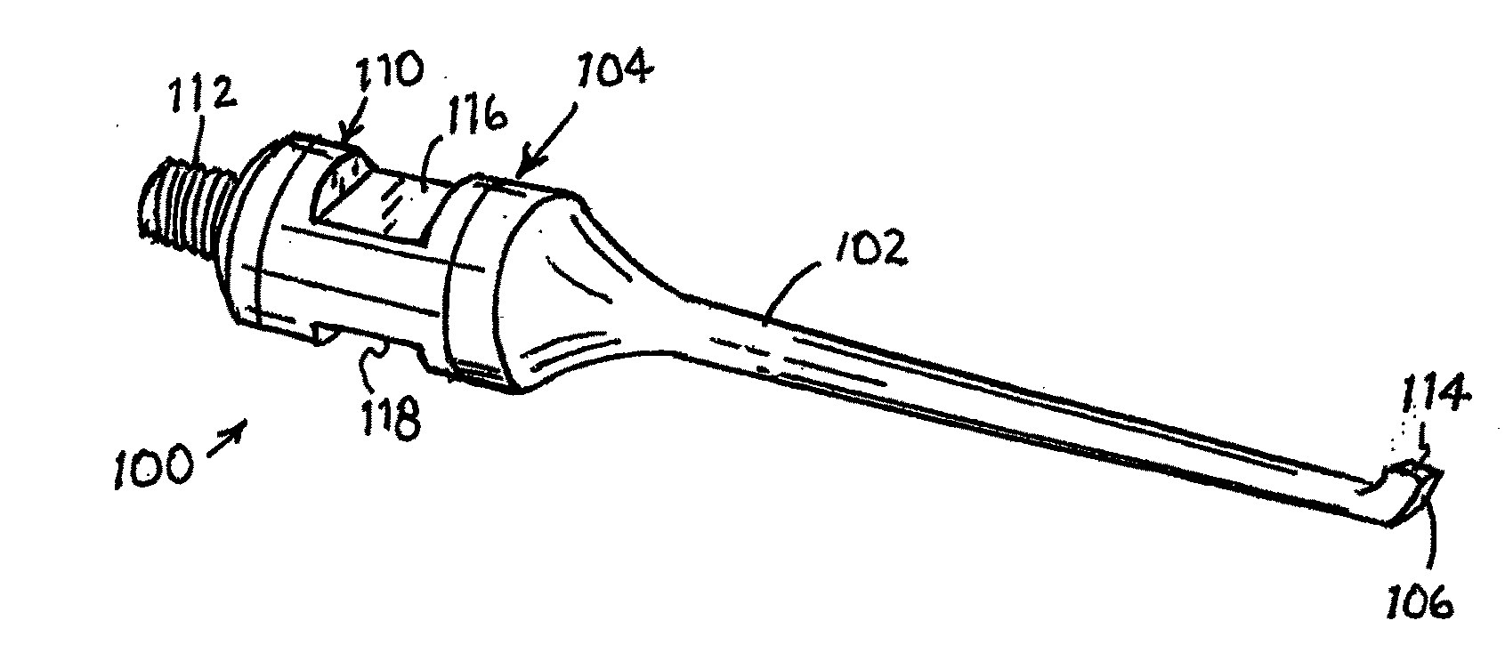
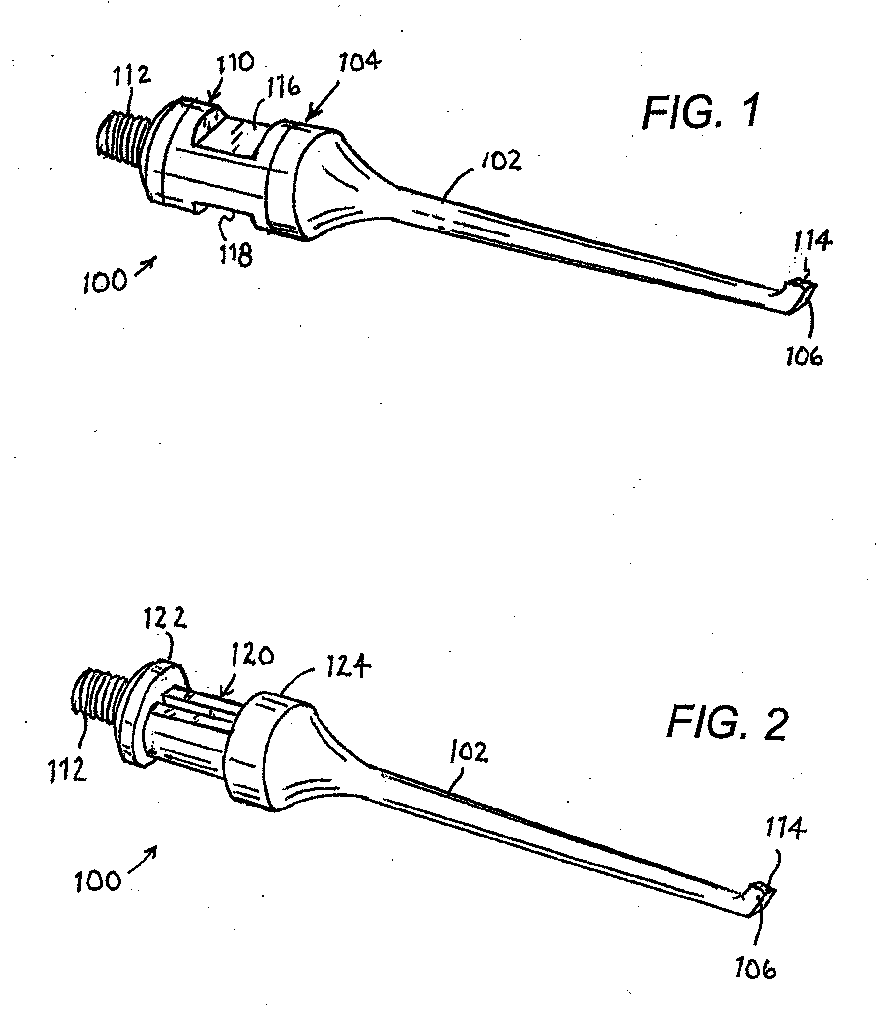
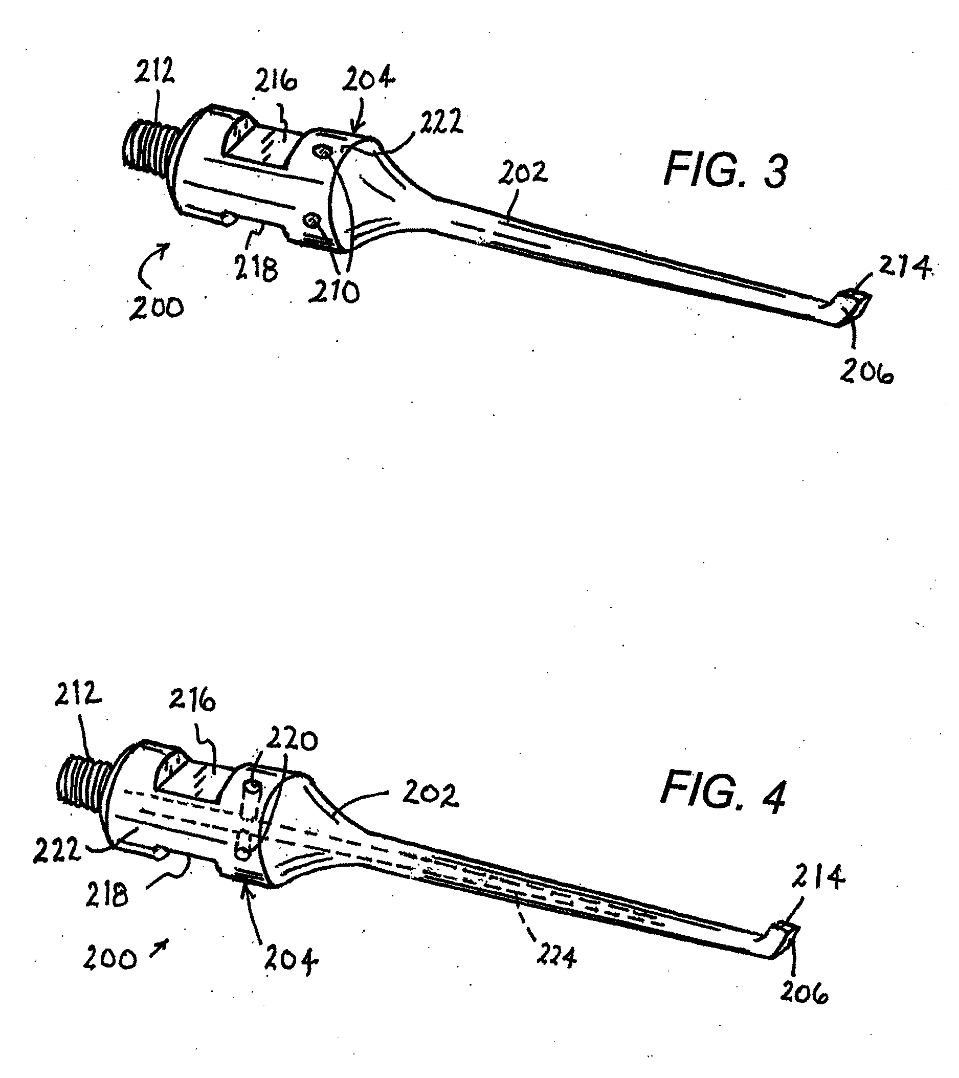
[0030]As depicted in FIG. 1, an ultrasonic medical probe 100 with a re-use failsafe structure includes a horn or shaft 102, a shank 104 at a proximal end of the shaft 102, an eccentric probe head 106 at a distal end of the horn or shaft 102, opposite the shank 104, and a polymeric component 110 fixed to and incorporated into the shank 104. Shank 104 is provided at a proximal end opposite the horn or shaft 102 with an externally threaded connector 112 for attaching the probe 100 to a source of ultrasonic vibratory energy. Typically, the probe 100 is connected, prior to use of the instrument in a surgical procedure, to a piezoelectric crystalline transducer stack housed in a handle. The transducer stack or array is electrically connectable to a generator of an alternating waveform of a predetermined ultrasonic frequency so as to generate an ultrasonic standing wave in probe 100. Probe head 106 has an operative or effector surface 114 that is placed into contact with organic tissues of...


PUM

PropertyMeasurementUnit
ultrasonic vibratory energyaaaaaaaaaa
outer diameteraaaaaaaaaa
polymericaaaaaaaaaa

Abstract

An ultrasonic medical probe has a horn or shaft, a shank at a proximal end of the shaft, a probe head at a distal end of the horn or shaft, opposite the shank, and at least one polymeric component fixed to at least one of the horn or shaft, the shank, and the probe head. The shank is provided at a proximal end opposite the horn or shaft with an externally threaded connector for attaching the probe to a source of ultrasonic vibratory energy. The polymeric component is of a composition that transmits and is essentially impervious to ultrasonic vibratory energy but that degrades or decomposes upon exposure to a source of extreme energy (other than ultrasonic vibratory energy), rendering the probe inoperative for use.

Description

BACKGROUND OF THE INVENTION[0001]This invention relates to an ultrasonic medical tool or probe. More particularly, this invention relates to such a tool or probe with one or more failsafe components for ensuring sterile use of the tool or probe. This invention also relates to an associated medical method.[0002]It is well known that hospitals routinely subject medical instruments, particularly surgical instruments, to sterilization procedures such as autoclaving, in order to enable or justify re-use of the instruments. It is not so well known that autoclaving and other sterilization procedures are far from effective in ensuring sterility. Many patients, particularly those undergoing invasive surgical procedures are subject to risk from improperly or incompletely sterilized instruments.[0003]The problem of sterilizing surgical instruments is particularly difficult when the instruments are elongate probes that are provided with a narrow channel or lumen, for instance, for irrigation or...

Claims


Application Information

Patent Timeline
Patent Type & Authority Applications(United States)
IPC IPC(8): A61N7/00A61L2/07
CPCA61L2/07A61N7/00A61B17/320068A61B2090/0814A61B2090/0807A61B2017/32007
Inventor ISOLA, SCOTTDARIAN, ALEXANDERVOIC, DANMANNA, RONALD
Owner MISONIX INC
Learn More