Rotating electric machine with a built-in control device and electric power assist steering system
a technology of electric motors and control devices, which is applied in the direction of electrical steering, electrical steering, and association with control/drive circuits, etc., can solve the problems of increasing the size and weight of electric rotation machines, the distance between heat sinks and control substrates is large, and the protruding portion is large in length, so as to reduce the number of components and shorten the size towards the shaft direction , the effect of reducing the number of components
- Summary
- Abstract
- Description
- Claims
- Application Information
AI Technical Summary
Benefits of technology
Problems solved by technology
Method used
Image
Examples
embodiment 1
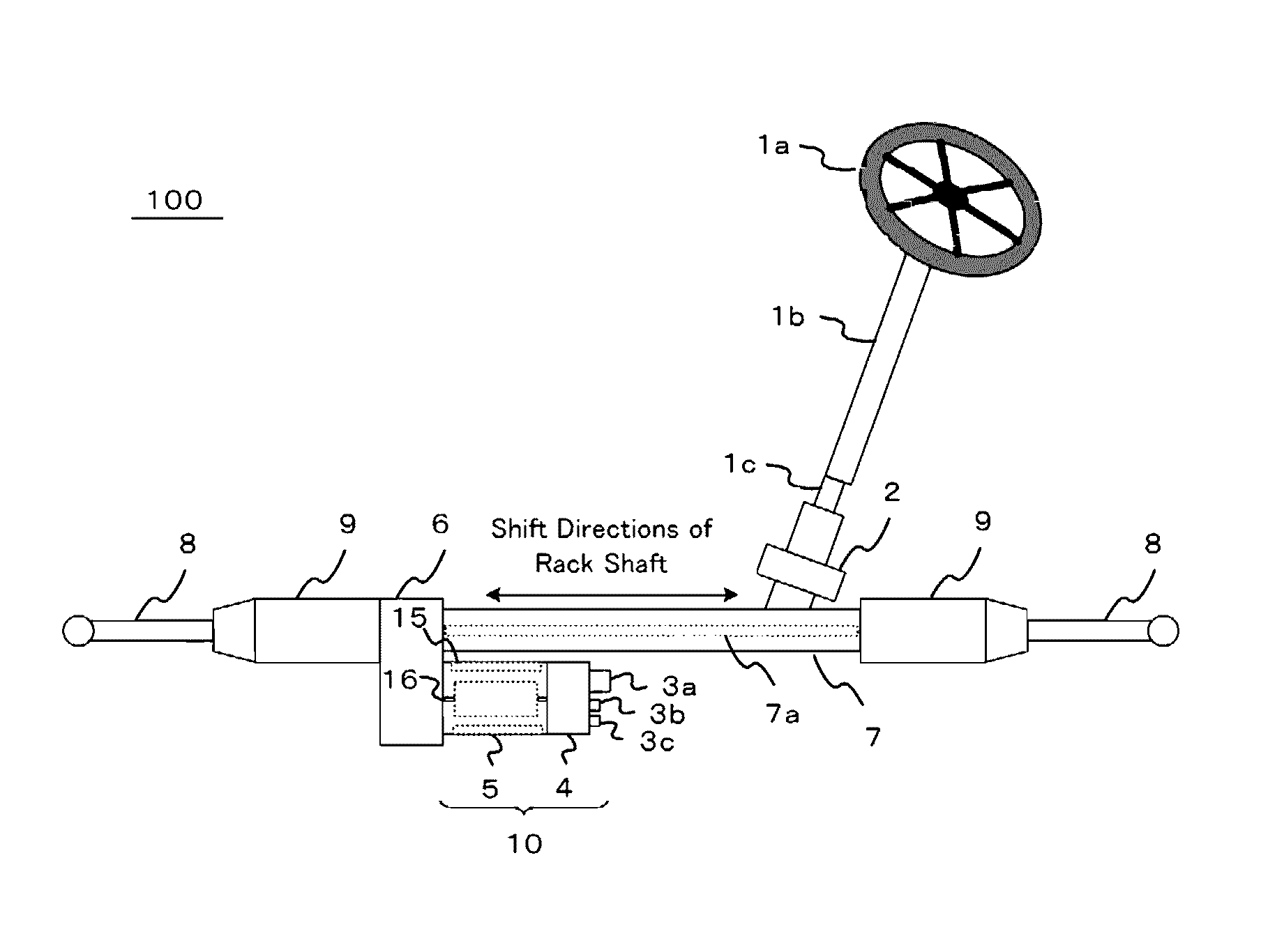
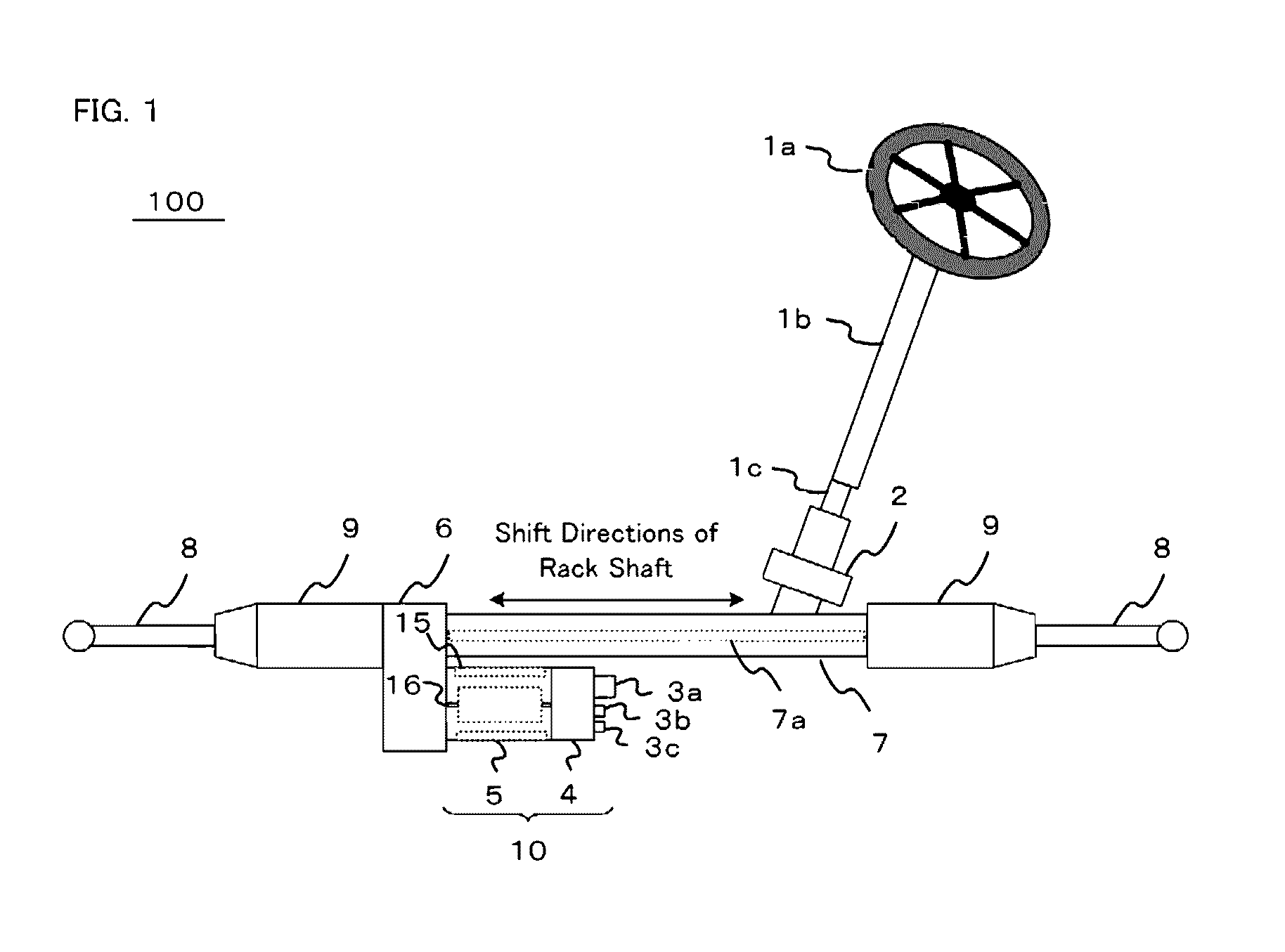
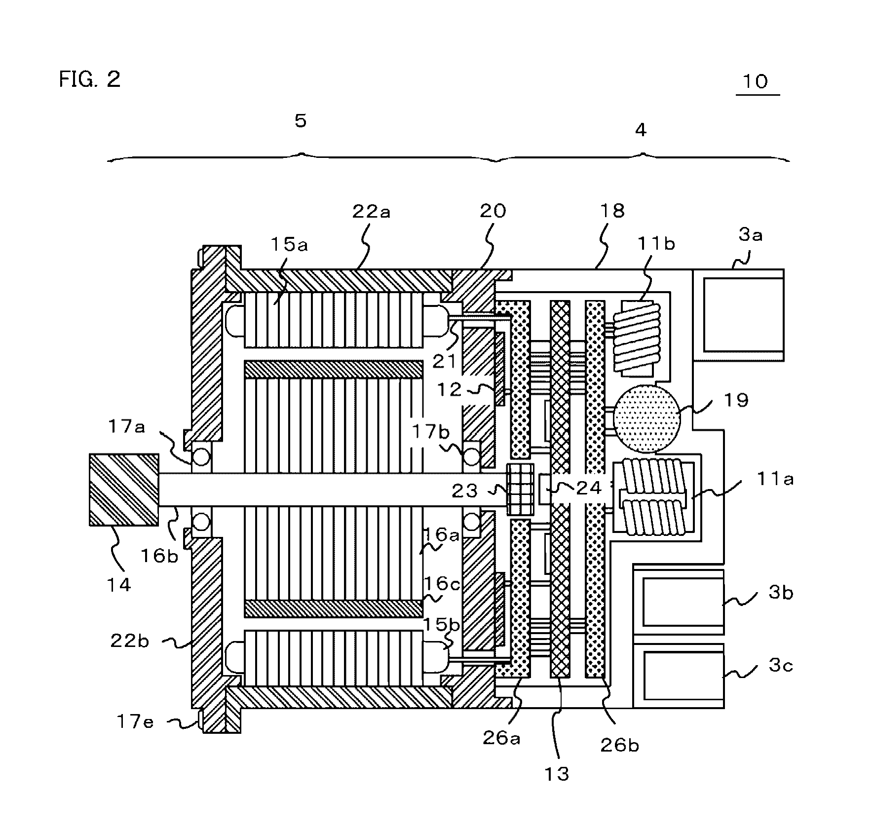
[0070]FIG. 1 is an explanatory drawing of the electric power assist steering system 100 for an automobile, in accordance with the embodiments of the present invention. A control device 4 and a motor unit 5 are combined together to build a rotating electric machine 10. Electric power from a battery or an alternator is supplied, by way of a connector 3a, to the control device 4 of the rotating electric machine 10. The motor unit 5 of the rotating electric machine 10 includes a stator 15 and a rotor 16. When a driver turns a steering wheel 1a, torque is transmitted, by way of a steering shaft 1b, to a shaft 1c. A torque sensor 2 detects the torque (a torque signal) and converts it into an electric signal. The electric signal is transmitted, by way of a connector 3b, to the control device 4 of the rotating electric machine 10. On the other hand, automobile information like car speed and others is converted into electric signals and is transmitted, by way of a connector 3c, to the contro...
embodiment 2
[0110]FIG. 21A and FIG. 21B are illustrative drawings of the rotating electric machine in accordance with Embodiment 2 of the present invention. The structure of a heat sink is basically the same as that of Embodiment 1. As shown in the drawing, the heat sink takes a configuration in which three motor terminals 21 pass through a single electric wiring through hole 20d. A control substrate 13, having parts of small current use on the rear side, is provided closely to a heat sink 20. The heat sink has a smaller number of holes and then, the volume of the heat sink is increased. Accordingly, the heat sink is improved in heat capacity and the switching elements are improved in cooling performance. By the way, here is provided a case where the motor terminals pass through the electric wiring through hole. Electric wirings, such as other signal wires, cables and the like, which connect between the rotating electric machine and the control device, may pass through the electric wiring throu...
embodiment 3
[0111]FIG. 22 is an illustrative drawing of the rotating electric machine in accordance with Embodiment 3 of the present invention. The structure of a rotating electric machine is basically the same as that of Embodiment 1. As shown in the drawing, the rotating electric machine takes a configuration in which three phase connections of an armature winding are connected to motor terminals 21 by way of a ring like connection plate 25. In the armature winding of the rotor core 15a, windings are connected each other and constitute a three phase connection. The connection plate 25 is disposed between the motor terminals 21 and the armature winding 15b.
PUM
 Abstract
Description
Claims
Application Information
 - R&D
- Intellectual Property
- Life Sciences
- Materials
- Tech Scout
- Unparalleled Data Quality
- Higher Quality Content
- 60% Fewer Hallucinations
Browse by: Latest US Patents, China's latest patents, Technical Efficacy Thesaurus, Application Domain, Technology Topic, Popular Technical Reports.
© 2025 PatSnap. All rights reserved.Legal|Privacy policy|Modern Slavery Act Transparency Statement|Sitemap|About US| Contact US: help@patsnap.com


