
Virtual and augmented reality systems and methods

a virtual reality and augmented reality technology, applied in the field of virtual reality and augmented reality imaging and visualization systems, can solve the problems of mass production, inability to meet the needs of mass production, and the structure of liquid crystal gratings with pbpe structures, and achieve the effects of high wavelength sensitivity of pbpe structures, low sensitivity to angle of incidence, and high diffraction efficiency

Active Publication Date: 2017-01-12
MAGIC LEAP
View PDF9 Cites 180 Cited by
  • Summary
  • Abstract
  • Description
  • Claims
  • Application Information

AI Technical Summary

Benefits of technology

The patent describes methods for making liquid crystal devices by depositing material on a substrate and using an imprint pattern to align the molecules of the liquid crystal. These methods can be used to create devices with layers of liquid crystal material and features that are smaller than the wavelength of visible light. The devices can include gratings with metasurface or metamaterials liquid crystal gratings that combine the benefits of traditional liquid crystal gratings with the properties of the PBPE structures. The methods can also be used to make polarizers that are more transparent than existing ones. Overall, the patent provides new ways for making liquid crystal devices with small features and high efficiency.

Problems solved by technology

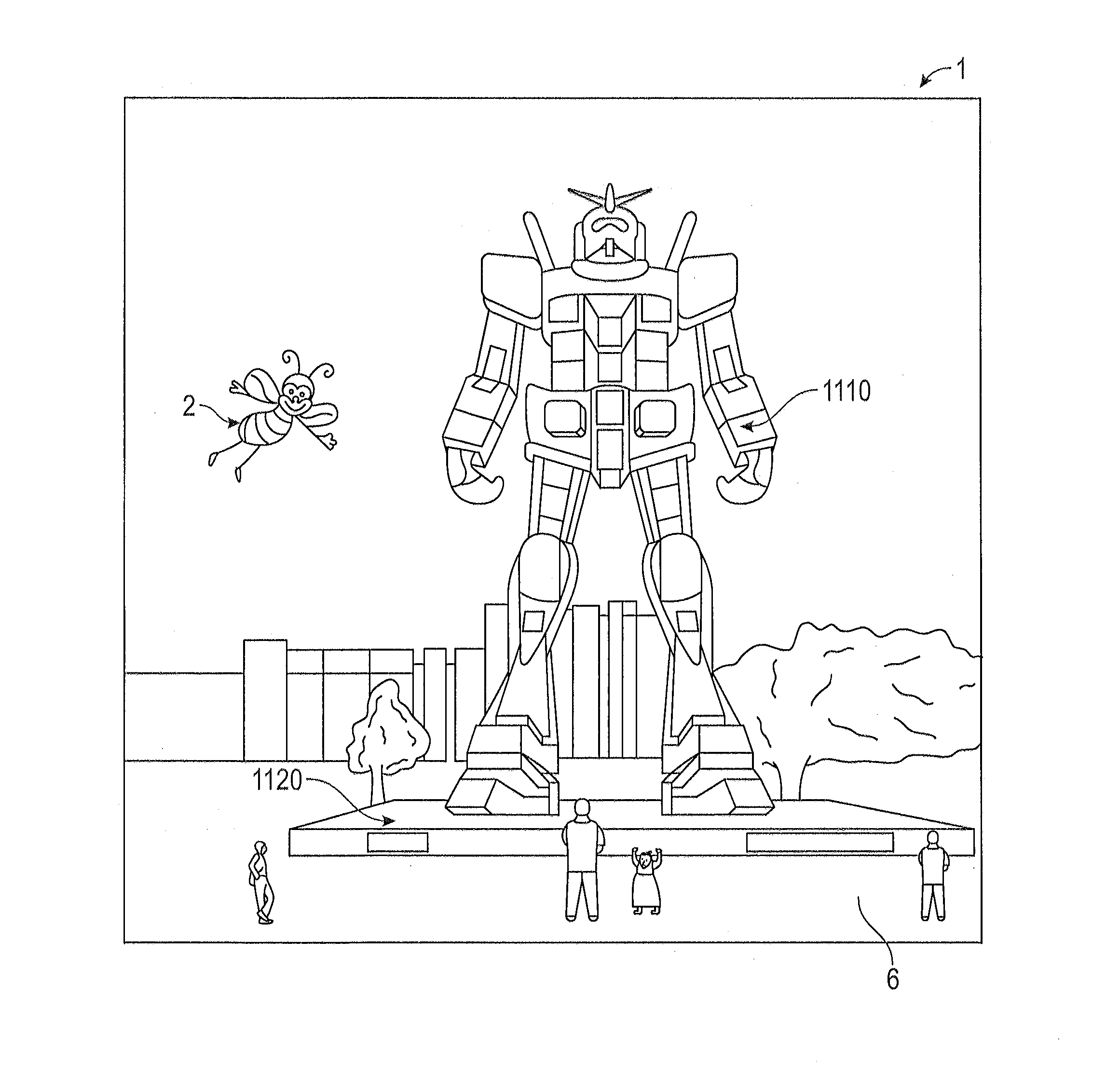
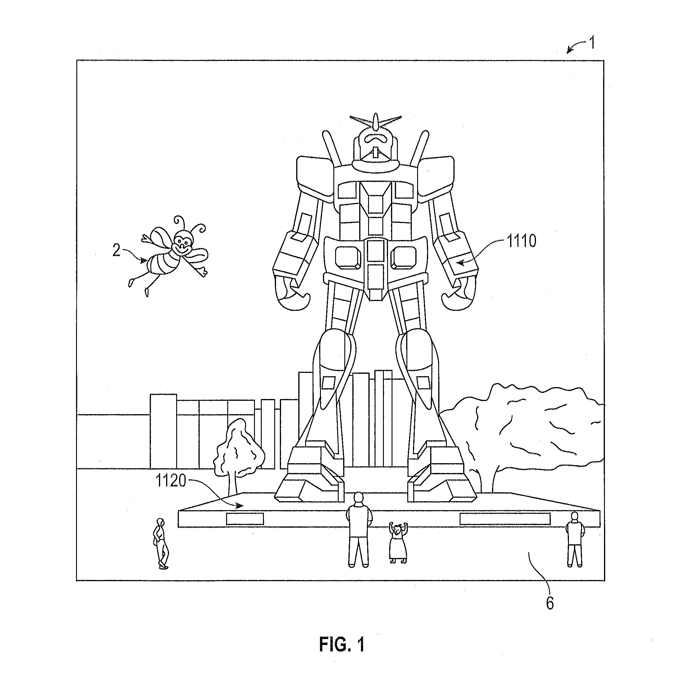
Because the human visual perception system is complex, it is challenging to produce a VR or AR technology that facilitates a comfortable, natural-feeling, rich presentation of virtual image elements amongst other virtual or real-world imagery elements.
Using the various methods of manufacturing described herein, liquid crystal gratings with PBPE structures can be mass-produced which may not be possible using the existing methods of disposing PBPE structures on liquid crystal materials.

Method used


Image

  • Virtual and augmented reality systems and methods
  • Virtual and augmented reality systems and methods
  • Virtual and augmented reality systems and methods

Examples


Embodiment Construction

[0047]Embodiments disclosed herein include optical systems, including display systems, generally. In some embodiments, the display systems are wearable, which may advantageously provide a more immersive VR or AR experience. For example, displays containing a stack of waveguides may be configured to be worn positioned in front of the eyes of a user, or viewer. In some embodiments, two stacks of waveguides, one for each eye of a viewer, may be utilized to provide different images to each eye.

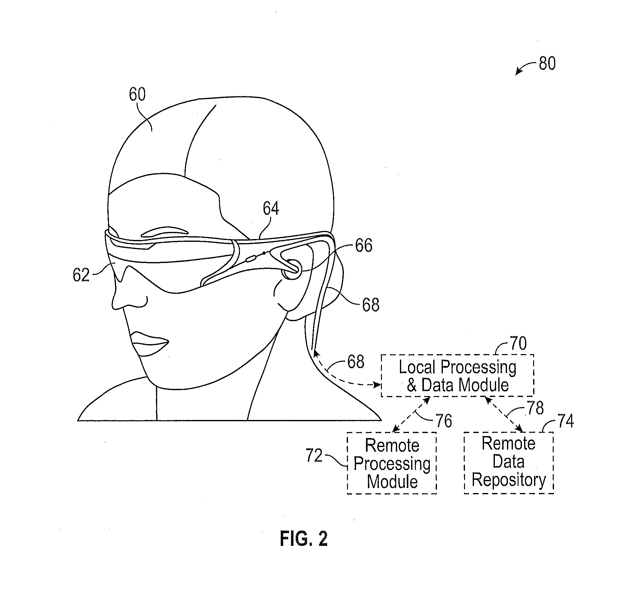
[0048]FIG. 2 illustrates an example of wearable display system (80). The display system (80) includes a display (62), and various mechanical and electronic modules and systems to support the functioning of that display (62). The display (62) may be coupled to a frame (64), which is wearable by a display system user or viewer (60) and which is configured to position the display (62) in front of the eyes of the user (60). In some embodiments, a speaker (66) is coupled to the frame (64) and positione...


PUM


Abstract

Methods of manufacturing a liquid crystal device including depositing a layer of liquid crystal material on a substrate and imprinting a pattern on the layer of liquid crystal material using an imprint template are disclosed. The liquid crystal material can be jet deposited. The imprint template can include surface relief features, Pancharatnam-Berry Phase Effect (PBPE) structures or diffractive structures. The liquid crystal device manufactured by the methods described herein can be used to manipulate light, such as for beam steering, wavefront shaping, separating wavelengths and / or polarizations, and combining different wavelengths and / or polarizations.

Description

PRIORITY CLAIM[0001]This application claims the benefit of priority under 35 USC §119(e) of U.S. Provisional Application No. 62 / 175,994 filed on Jun. 15, 2015 and of U.S. Provisional Application No. 62 / 180,551 filed on Jun. 16, 2015. Each of the above-identified applications is incorporated by reference herein in its entirety.INCORPORATION BY REFERENCE[0002]This application incorporates by reference in its entirety each of the following U.S. Patents and Patent Applications: U.S. Pat. No. 6,334,960, issued on Jan. 1, 2002, titled “Step and Flash Imprint Technology;” U.S. Pat. No. 6,873,087, issued on Mar. 29, 2005, titled “High-Precision Orientation, Alignment and Gap control Stages for Imprint Lithography Processes;” U.S. Pat. No. 6,900,881, issued on May 31, 2005, titled “Step and Repeat Imprint Lithography;” U.S. Pat. No. 7,070,405, issued on Jul. 4, 2006, titled “Alignment Systems for Imprint Lithography;” U.S. Pat. No. 7,122,482, issued on Oct. 17, 2006, titled “Methods for Fabr...

Claims


Application Information

Patent Timeline
IPC IPC(8): G02F1/13G02B27/01G02B30/60
CPCG02B27/0172G02F1/1326G02B5/1809G02B26/103G02B5/3016G02B27/283G02B1/002G02B6/004G02B27/0081G02B5/1833G02B6/0076G02B27/1006G02B6/0016G02B27/4272G02B2027/0185G02B2027/0125G02B2027/0112G02F1/1303
Inventor KLUG, MICHAEL ANTHONYSCHOWENGERDT, BRIAN T.MILLER, MICHAEL NEVINSINGH, VIKRAMJITPEROZ, CHRISTOPHEST. HILAIRE, PIERRESUN, JIE
Owner MAGIC LEAP
Learn More