
Metal 3D printer

a 3d printer and metal technology, applied in the field of metal 3d printers, can solve the problems of not spreading to the entire space of the molding chamber, the maximum supply amount of inert gas is not practicable, and the powder layer may be disturbed, so as to achieve enhanced ventilation capacity of the molding chamber, the effect of increasing the discharge amount of fumes and high efficiency

Active Publication Date: 2017-01-19
SODICK CO LTD
View PDF2 Cites 37 Cited by
  • Summary
  • Abstract
  • Description
  • Claims
  • Application Information

AI Technical Summary

Benefits of technology

The invention is a metal 3D printer that uses a suction device to remove fumes and debris from the laser beam's path during a molding process. This improves production efficiency and reduces the amount of fine metal particles that can damage the quality and safety of the finished product. Additionally, the suction device ensures a steady flow of clean inert gas, even when the recoater head is close to the suction port. Overall, this invention allows for quicker and more efficient removal of fumes from the molding chamber, ultimately resulting in better quality and safety.

Problems solved by technology

However, there is a practical limit to the maximum supply amount of the inert gas.
If the opening of the ventilation channel is close to the irradiation region, the powder layer may be disturbed.
Besides, if the openings of the two ventilation channels are too close to each other in the chamber, fresh inert gas may be sucked out immediately and may not spread to the entire space of the chamber.
When the amount of the fumes increases, it will take a long time to eliminate the fumes in the chamber and the production efficiency will drop.

Method used


Image

  • Metal 3D printer
  • Metal 3D printer
  • Metal 3D printer

Examples


Embodiment Construction

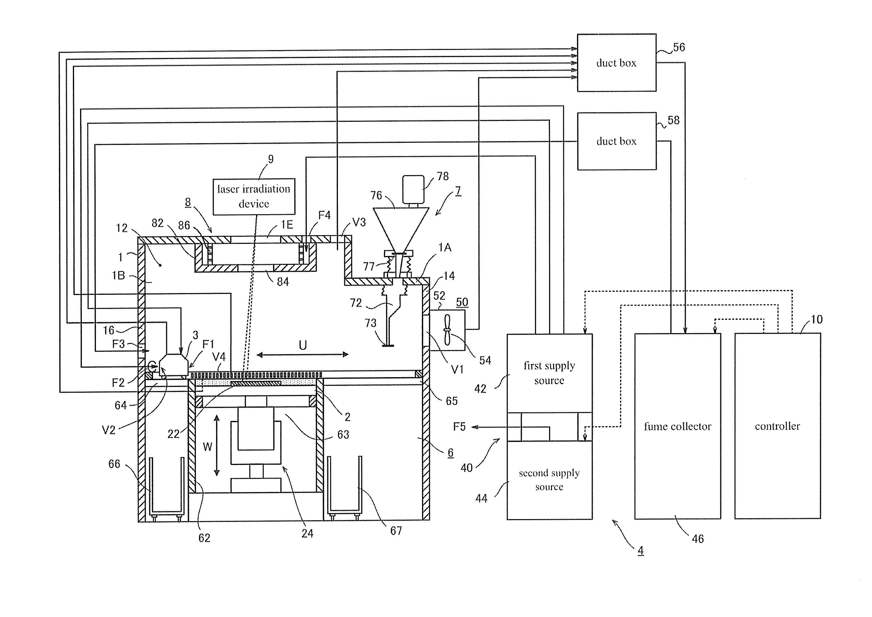
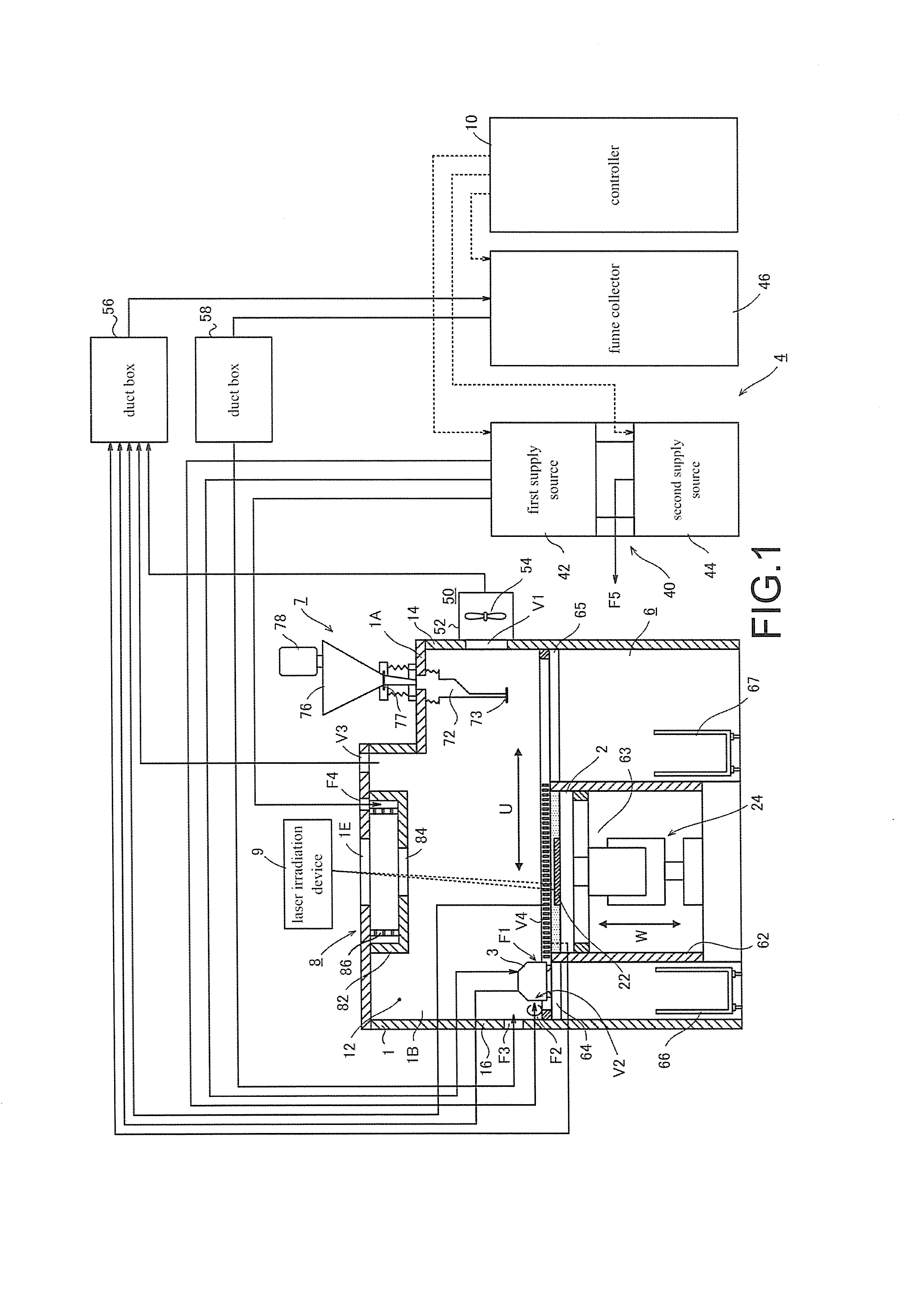
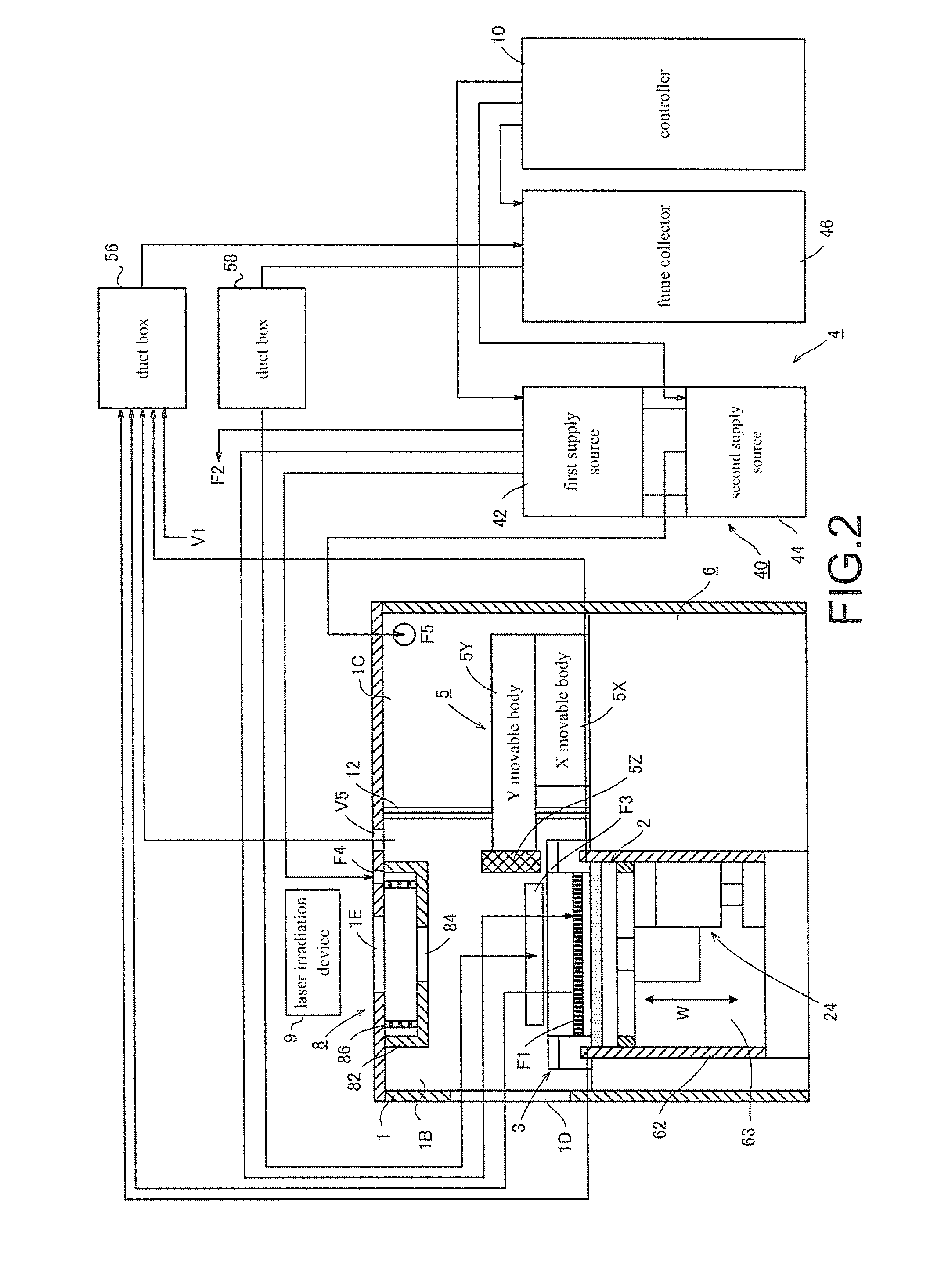
[0030]An embodiment of the invention is described in detail with reference to the accompanying figures. The dotted lines in FIG. 1 and FIG. 2 indicate a signal line while the dotted lines in FIG. 3 indicate an irradiation path of a laser beam.

[0031]FIG. 1 and FIG. 2 illustrate a metal 3D printer for laminate-molding a three-dimensional object by repeatedly sintering metal powder. The metal 3D printer includes a housing 1, a recoater head 3, a material supply device 7, an inert gas supply device 4, a power supply, a controller 10, and a fume collector 46. The power supply, the controller 10, and the fume collector 46 are located in the rear of the housing 1.

[0032]The housing 1 is a means for forming an environment where an oxygen concentration is less than a predetermined value. The housing 1 includes a ceiling and four side walls and forms a sealed chamber. The sealed chamber is divided into a molding chamber 1B on the front side and a drive chamber 1C on the rear side by a bellows ...


PUM


Abstract

A metal 3D printer includes: a housing (1) forming a molding chamber (1B); a recoater head (3) reciprocating in the direction of a horizontal U axis in the molding chamber to form a powder layer of a metal; a laser irradiation device (9) irradiating an irradiation region in the powder layer with a laser beam to form a sintered layer; and an inert gas supply device (4). The inert gas supply device includes: a first suction port (V1) disposed on one (14) of the side walls facing each other in the direction of the U axis, which is far away from the irradiation region; a first blowout port (F1) disposed on a side of the recoater head to face the first suction port; and a second blowout port (F2) disposed to face the first suction port across the irradiation region.

Description

BACKGROUND OF THE INVENTION[0001]Field of the Invention[0002]The invention relates to a metal 3D printer for laminate-molding a three-dimensional object as a product by repeatedly sintering metal powder in a molding chamber. In particular, the invention relates to a metal 3D printer that is provided with a device for removing fumes generated by sintering of the metal powder from the molding chamber.[0003]Description of Related Art[0004]The conventional metal 3D printer forms a thin powder layer by spreading metal powder uniformly on a table, and irradiates a specific irradiation region in the powder layer with a laser beam, so as to form a sintered layer. A desired three-dimensional object is formed by stacking a large number of the sintered layers. The metal 3D printer determines the irradiation region of the laser beam for each division layer that is obtained by dividing the three-dimensional object at a predetermined height. In other words, the metal 3D printer decides the irradi...

Claims


Application Information

Patent Timeline
IPC IPC(8): B22F3/105B33Y70/00B33Y50/02B33Y30/00B33Y40/00
CPCB22F3/1055B33Y30/00B22F2003/1057B33Y50/02B33Y70/00B33Y40/00B22F2999/00B22F10/00B22F10/77B22F12/38B22F10/28B22F12/52B22F10/322B22F12/70B22F12/67B22F2201/10B22F2203/00B29C64/214B29C64/371B29C64/25Y02P10/25
Inventor KAWADA, SHUICHIOKAZAKI, SHUJI
Owner SODICK CO LTD
Learn More