
Composite target and x-ray tube with the composite target

a composite target and target technology, applied in the direction of x-ray tube target and convertor, x-ray tube target material, nuclear engineering, etc., can solve the problems of inconvenient use, difficult to obtain the required x-ray energy spectrum distribution, and unnecessary radiation absorbed by the human body, and achieve the effect of sufficient long service li

Active Publication Date: 2017-01-19
NANORAY BIOTECH CO LTD
View PDF3 Cites 14 Cited by
  • Summary
  • Abstract
  • Description
  • Claims
  • Application Information

AI Technical Summary

Benefits of technology

This patent describes a new composite target for an X-ray tube that can generate a variety of energy spectrum distributions with a long service life. The composite target includes a target body and an interposing layer that moves the peak of the X-ray energy spectrum towards high energy direction and filters low energy photons. The interposing layer can also be increased in thickness to increase the amount of high energy photons generated. The X-ray tube with this composite target can provide a variety of energy spectrum distributions and has a long service life. The invention also provides a method for setting multiple film layers in the target body to achieve a desired energy spectrum distribution and a protective layer to protect the composite target from excessive electron damage.

Problems solved by technology

When it is desired to use different bremsstrahlung distribution, it is required to correspondingly replace the target with different thickness, so that the use is quite inconvenient.
However, it is still difficult to obtain the required X-ray energy spectrum distribution.
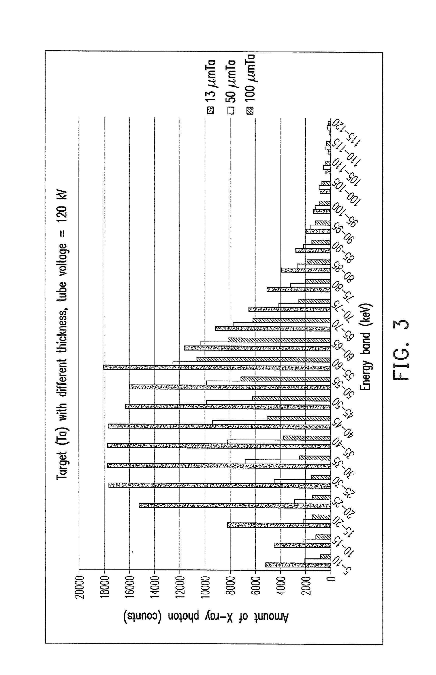
However, as shown in FIG. 4, the amount of the low energy photon of the X-ray of the reflection type X-ray tube is usually too much, which causes unnecessary radiation absorbed dose for human body.
Additionally, if the target is bombarded by the electron for a long time, the loss of the surface material of the target is generated.

Method used


Image

  • Composite target and x-ray tube with the composite target
  • Composite target and x-ray tube with the composite target
  • Composite target and x-ray tube with the composite target

Examples


Embodiment Construction

[0036]The composite target and the X-ray tube with the composite target provided by the invention can provide a variety of X-ray energy spectrum distributions to meet various actual needs. Embodiments of the invention are illustrated referring to the following figures.

[0037]FIG. 5 is a schematic diagram of an X-ray tube with a composite target of a preferred embodiment of the invention. Here, the composite target is used in the transmission type X-ray tube as an example to illustrate. However, the composite target is not limited to be used in the transmission type X-ray tube, it can be used in the reflection type X-ray tube, or any other type of X-ray tube.

[0038]Referring to FIG. 5, an X-ray tube includes a casing 310, an anode 320, a cathode 330, and a power source 340. The anode 320 is disposed at the casing 310. A composite target 350 is disposed on the anode 320. The composite target 350 is interacted with an electron 360 to generate an X-ray 370, and an energy of the electron 3...


PUM


Abstract

A composite target is provided and is interacted with an electron to generate an X-ray, and an energy of the electron can be changed by controlling a tube voltage at least. The composite target includes a target body and an interposing layer which is connected with the target body. The interposing layer moves a highest peak of an energy spectrum of the X-ray toward a high energy direction. The interposing layer may be a single metal or a metal mixture. Not only a low energy photon of the X-ray can be filtered by the interposing layer, but also a distribution of the low energy photon of the X-ray can be increased by increasing a thickness of the interposing layer. As the tube voltage is enhanced, an amount of a high energy photon of the X-ray generated is dramatically increased. An X-ray tube containing the above composite target is also provided.

Description

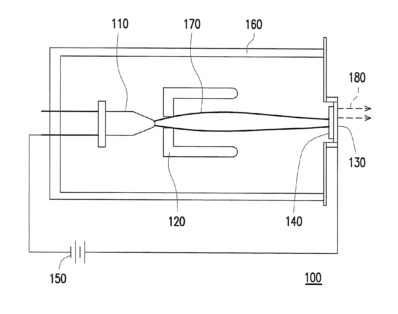
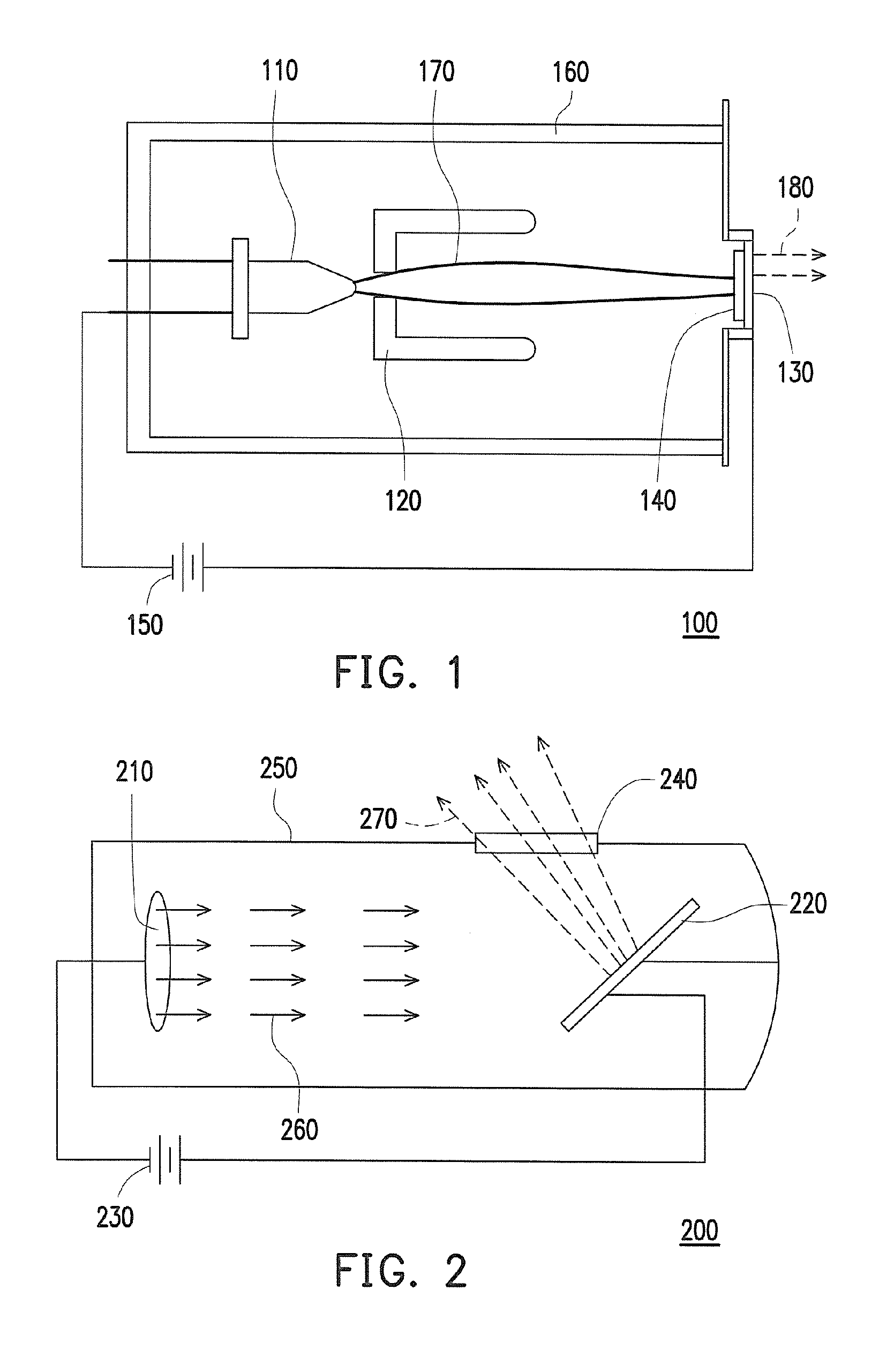
CROSS-REFERENCE TO RELATED APPLICATION[0001]This application claims the priority benefits of U.S. provisional application Ser. No. 62 / 148,755, filed on Apr. 17, 2015. The entirety of the above-mentioned patent application is hereby incorporated by reference herein and made a part of specification.BACKGROUND OF THE INVENTION[0002]Field of the Invention[0003]The invention relates to a target and an X-ray tube, and particularly relates to a composite target and an X-ray tube with the composite target.[0004]Description of Related Art[0005]An X-ray tube can be broadly divided into a transmission type X-ray tube and a reflection type X-ray tube, which is suitable for medical image, industrial testing, and other technical fields.[0006]FIG. 1 is a schematic diagram of a conventional transmission type X-ray tube. Referring to FIG. 1, a transmission type X-ray tube 100 includes a cathode 110, a focusing mechanism 120, an end window anode 130, a target 140, a power source supply 150, and a vac...

Claims


Application Information

Patent Timeline
IPC IPC(8): H01J35/08H01J35/06H01J35/14H05G1/32
CPCH01J35/08H05G1/32H01J2235/088H01J35/14H01J2235/081H01J35/06G21K1/10H01J2235/083H01J2235/086H01J35/116H01J2235/08
Inventor CHENG, CHI-CHIEH
Owner NANORAY BIOTECH CO LTD
Learn More