Cooling Device with Small Structured Rib-Dimple Hybrid Structures

a hybrid structure and cooling device technology, applied in the direction of machines/engines, stators, light and heating apparatus, etc., can solve the problems of increasing difficulty and cost of machining, affecting the heat transfer performance of half of the spherical dimple, and affecting the cooling effect of components, so as to improve the flow turbulence energy, improve the heat transfer performance of the upstream, and improve the flow field inside the dimple

Active Publication Date: 2017-02-02
SHANGHAI JIAO TONG UNIV
View PDF4 Cites 13 Cited by
  • Summary
  • Abstract
  • Description
  • Claims
  • Application Information

AI Technical Summary

Benefits of technology

[0020]In the present invention, when the cooling fluid flows into the cooling channel, each of the small structured ribs continuously destroys the flow boundary layer, creating a downwashing vortex behind each small structured rib, which will enhance the flow turbulence energy near the wall surface boundary layer upstream the dimple and suppress the generation of flow separation at the leading edge of the dimple, thereby improving the heat transfer performance of the upstream half dimpled wall surface. On the other hand, the flow field inside the dimple will be improved when the downwashing vortex flows into the dimple, in particular the front half zone of the dimple, thereby significantly improving the heat transfer performance in the dimple. The downwashing vortex can also improve the turbulent mixing strength of the flow attachment in the rear half of the dimple, thereby enhancing the heat transfer in this zone and at the downstream wall surface.
[0021]As a result of the above, the present invention has the following features: the small structured ribs are mounted on the upstream wall surface of the dimple in the present invention, the fluid passes through each of the small structured ribs to produce downwashing vortex, enhancing the flow turbulence energy in the boundary layer flow upstream the dimple and improving the flow field near the wall surface at the front half of the dimple and the turbulent mixing strength of the flow attachment in the rear half of the dimple, thereby enhancing the heat transfer at the upstream dimpled wall surface, interior and the downstream wall surface of the dimple. As compared with the existing dimple vortex generator, the cooling device with small structured rib-dimple hybrid structures in the present embodiment can overcome the defects residing in the existing dimple vortex generators that the flow turbulence energy is low in the boundary layer flow upstream the dimple, and the flow separation at the leading edge of the dimple easily happens, which lead to low heat transfer. So the present embodiment can significantly improve the comprehensive heat transfer performance, while reducing the flow rate of the cooling fluid under the same cooling load, thereby reducing the power consumption of the pump or blower. In addition, it is simple to have the small structured ribs mounted on the upstream wall surface of the dimple, therefore provides desirable implementability, which has a very important significance to practical applications of enhanced heat transfer or improving cooling performance.

Problems solved by technology

However, with the temperature parameters (>1600° C.) of modern gas turbines or aircraft engines being further improved, the application of the traditional cooling technologies by rib turbulators or pin fins alone has been difficult to sufficiently cool high-temperature components.
Although, overall, the spherical dimple vortex generators can significantly strengthen the convective heat transfer, the experimental and numerical calculation studies show that the front half of the spherical dimple has poor heat transfer performance due to the flow separation and low recirculation zone; and at the rear half of the dimple, strong vortex is formed due to the impact and the attachment of the fluid, and the heat transfer performance is greatly enhanced.
However, machining advanced complex teardrop dimple in turbine blades is no easy thing, and the difficulty and cost of machining will be increased, and these factors have limited the overall performance and practical application of the dimple vortex generators.

Method used


Image

  • Cooling Device with Small Structured Rib-Dimple Hybrid Structures
  • Cooling Device with Small Structured Rib-Dimple Hybrid Structures
  • Cooling Device with Small Structured Rib-Dimple Hybrid Structures

Examples


embodiment 1

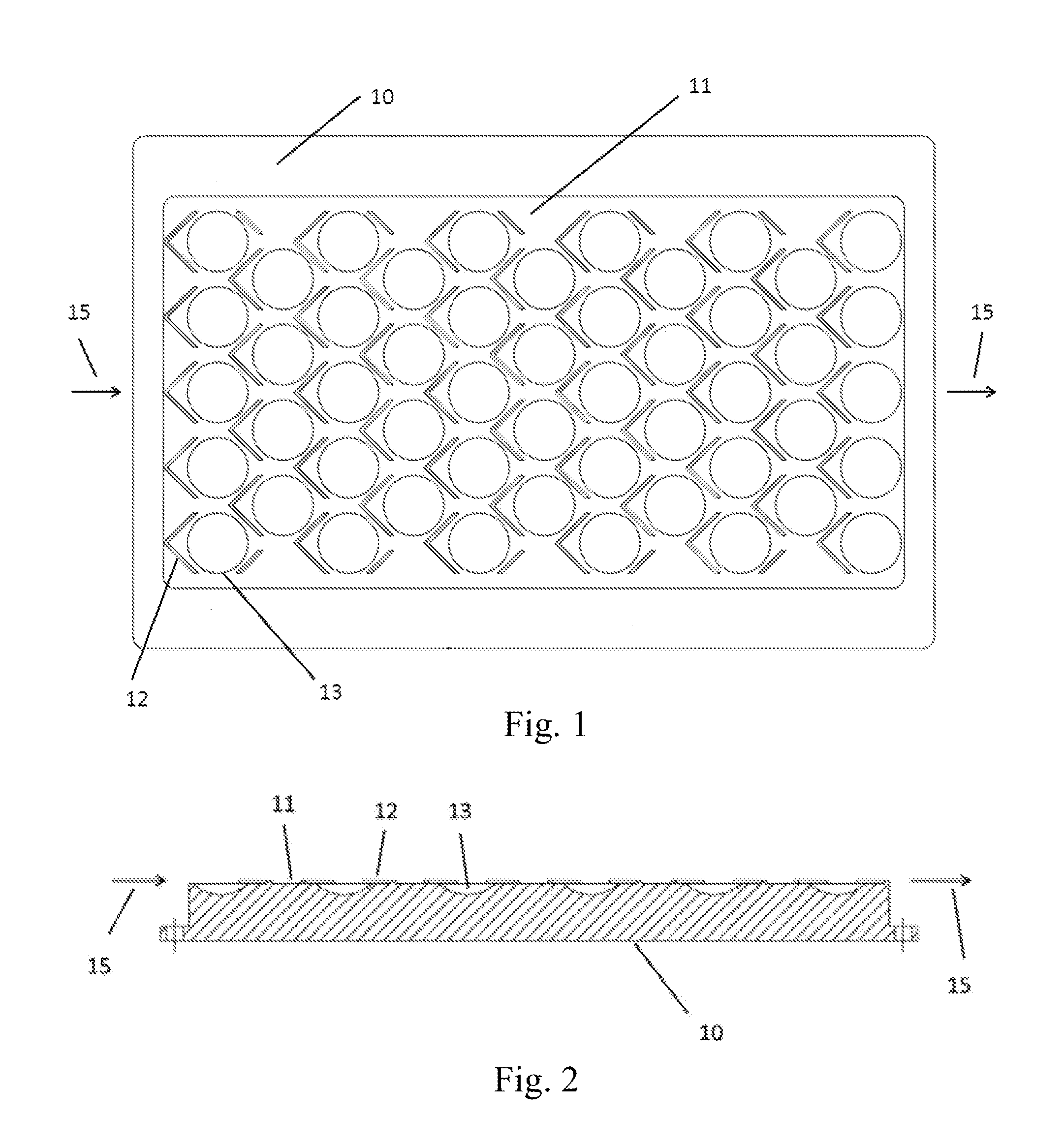
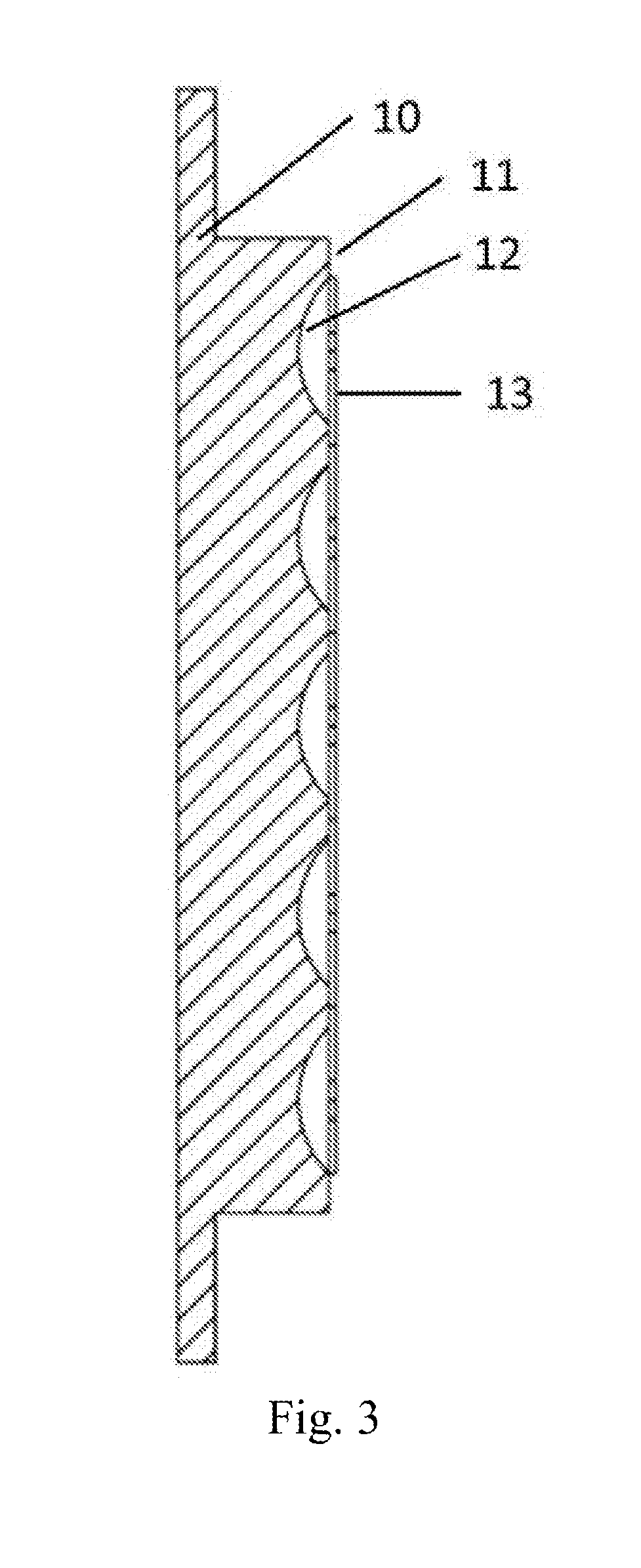
[0030]In this embodiment, as shown in FIGS. 1-3, a cooling device with small structured rib-dimple hybrid structures comprises a substrate 10, a cooling channel 11, a plurality of small structured ribs 12 and a plurality of dimples 13. The cooling channel 11 is disposed on the wall surface of the substrate 10, the plurality of dimples 13 are also disposed on the wall surface in a staggered arrangement, forming a dimple array, the upstream wall surface of each of the dimples being arranged with an small structured rib 12.

[0031]The plurality of small structured ribs 12 are formed on the wall surface of the substrate 10 through investment casting, milling or soldering, each of the small structured ribs 12 and the substrate 10 being made of high thermal conductivity materials. Each of the small structured ribs 12 is composed of one rib or two ribs forming a V-shape with an angle of 60 degree to 180 degree. The cross-section of the rib has a rectangular shape, the width of each rib is no...

embodiment 2

[0034]In this embodiment, as shown in FIGS. 1-3, a cooling device with small structured rib-dimple hybrid structures comprises a substrate 10, a cooling channel 11, a plurality of small structured ribs 12 and a plurality of dimples 13. The cooling channel 11 is disposed on the wall surface of the substrate 10, the plurality of dimples 13 are also disposed on the wall surface in a staggered arrangement, forming a dimple array, the upstream wall surface of each of the dimples being arranged with an small structured rib 12.

[0035]The plurality of small structured ribs 12 are formed on the wall surface of the substrate 10 through investment casting, milling or soldering, each of the small structured ribs 12 and the substrate 10 being made of high thermal conductivity materials. Each of the small structured ribs is composed of one rib or two ribs forming a V-shape with an angle of 30 degree to 180 degree. The cross-section of the rib has a rectangular shape, the height of each rib may be ...

embodiment 3

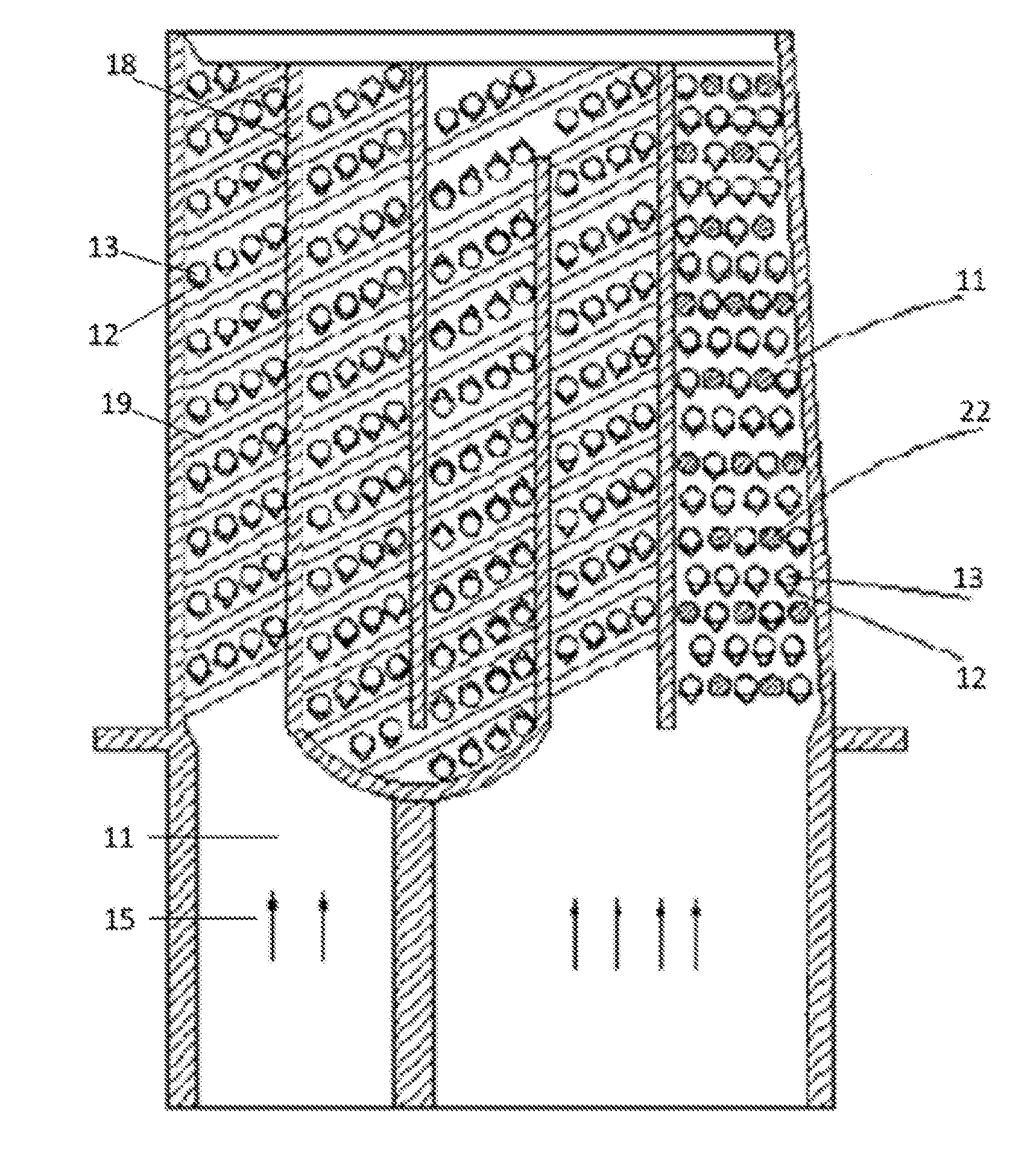
[0037]In this embodiment, as shown in FIGS. 5-7, a gas turbine blade with two hybrid cooling structures of rib-small structured rib-dimple and pin fin-small structured rib-dimple includes a cooling channel 11, a pressure side wall surface 20, a suction side wall surface 21, and further includes a plurality of ribs 19, a plurality of pin fins 22, a plurality of dimples 13 and a plurality of small structured ribs 12. The direction of arrow 15 indicates the flow direction of the cooling fluid. The cooling channel 17 is arranged between the pressure side wall surface 20 and the suction side wall surface 21, the plurality of ribs 19 are arranged inside the cooling channel 11 between the adjacent baffles 18, and the plurality of ribs 19 are inclined by the same angle along the flow direction. The upstream wall surface of each of the ribs 19 is arranged with a row of dimples 13.

[0038]The plurality of pin fins 22 and the plurality of dimples 13 are arranged at the trailing edge of the blade...


PUM


Abstract

A cooling device with small structured rib-dimple hybrid structures, comprising a substrate, a cooling channel, a plurality of small structured ribs and a plurality of dimples. The cooling channel, the plurality of small structured ribs and the plurality of dimples are all disposed on the wall surface of the substrate; the plurality of dimples are in a staggered arrangement or in a longitudinal arrangement, forming a dimple array; an upstream wall surface of each dimple or a plurality of dimples is provided with the small structured ribs, thus forming an small structured rib-dimple hybrid structure.

Description

FIELD OF THE INVENTION[0001]The invention relates to a cooling device, and particularly to a cooling device with small rib-dimple hybrid structures used for a high-temperature component in a gas turbine or an aero-engine. The invention can also be used in technical fields of air-conditioning heat exchanger, automobile heat exchanger, high power electronic device, etc. which require highly efficient heat transfer and cooling.DESCRIPTION OF THE PRIOR ART[0002]Highly efficient heat transfer and cooling technology is a necessary and key technology for a high-performance gas turbine or an aero-engine, which ensures the high-temperature component of the gas turbine to operate with high efficiency and reliability as well as a sufficient service life. The key high-temperature components which require highly efficient cooling in the gas turbine or an aero-engine usually include: turbine blades, combustion chambers, etc., with a traditional way of thermal protection by means of internal rib a...

Claims


Application Information

Patent Timeline
Patent Type & Authority Applications(United States)
IPC IPC(8): F01D5/18F01D9/06F23R3/00
CPCF01D5/187F23R3/005F01D9/065F23R2900/03045F05D2260/2212F05D2260/22141F05D2250/712F05D2250/241F05D2250/75F23R3/002Y02T50/60
Inventor RAO, YU
Owner SHANGHAI JIAO TONG UNIV
Why Eureka
Try Eureka