Engine device

Inactive Publication Date: 2017-02-02
YANMAR CO LTD
View PDF5 Cites 6 Cited by
  • Summary
  • Abstract
  • Description
  • Claims
  • Application Information

AI Technical Summary

Benefits of technology

The present invention provides an exhaust gas purification device for engines that has a single component structure and reduced complexity in the pipe structure. The device includes a first case for removing particulate matter and a second case for removing nitride oxides. A supporting stand is integrally arranged with the first, second, and urea mixing pipes, forming a simple exhaust gas purification device that is mounted on the engine. The exhaust gas purification device is mounted in a posture with the transfer direction of exhaust gas parallel to the engine output shaft, and the device is securely mounted on supporting legs that are adhered to the engine oil pan. This structure simplifies the installation of the device and improves workability in terms of the exhaust gas pipes.

Problems solved by technology

When the DPF case and the SCR case are assembled apart from the engine, the temperature of the exhaust gas supplied from the engine to the DPF case or the SCR case is reduced, and the reproduction of the diesel particulate filter or chemical reaction such as the action of selective catalyst reduction is defectively made, which leads to a problem in that a specific device for maintaining the exhaust gas at a high temperature in the SCR case needs to be provided.
However, the mounting surface of the object to be installed needs to be formed horizontally (flat), and therefore there is a problem in that it is difficult to support the supporting posture of the DPF case and the SCR case at a predetermined posture due to machining errors of mounting components such as the base frame.
On the other hand, when the DPF case and the SCR case are assembled in close proximity to the engine, the temperature of the exhaust gas supplied from the engine to the SCR case is reduced, and the temperature of the exhaust gas in the SCR case is easily maintained at a high temperature, but it is necessary to secure an installation space for the SCR case on the lateral side of the engine, which leads to problems in that it is difficult to constitute a miniaturized engine room, and the DPF case, the SCR case, or the like cannot be supported in a compact way.
Furthermore, as disclosed in Japanese Unexamined Patent Application Publication No. 2008-8516, in conventional technologies in which a diesel engine as a driving source for the air conditioning apparatus is mounted on the container for transporting goods, the DPF case and the SCR case can be provided on the upper portion of the diesel engine and the like, but the installation space of the diesel engine cannot be provided in a compact way.
Also, the external size of the container for transporting goods is defined for each intended purpose, and therefore the external size cannot be increased, which leads to a problem in that it is necessary to reduce the carrying capacity of goods of the container, and the like.
Also, when the container is stored for a long period of time in a state where the container for transporting goods is operated, or when the container in a state of operation is transferred for a long distance, the engine is successively operated for a long period of time in a state of rotation at a relatively low speed, which leads to a problem in that the exhaust gas purification temperature of the exhaust gas purification device cannot be easily maintained at a temperature or higher at which the exhaust gas can be successively purified.
When the engine is successively operated for a long period of time, an oil pan having large capacity is required.
However, in consideration of the costs of molding the oil pan, there is a problem in that rigidity is deficient, and the vibration of the engine is prone to transmit.

Method used


Image

  • Engine device
  • Engine device
  • Engine device

Examples


first embodiment

[0043]The structure of the stationary power generation work machine 70 of the first embodiment will be described referring to FIGS. 4 to 6. As illustrated in FIGS. 4 to 6, a machine casing 2 formed in a quadrilateral box shape is placed on a machine casing stand 1. A diesel engine 3 is installed in the center in the interior of the machine casing 2 on the upper surface of the machine casing stand 1. A radiator 6 is arranged on the installation side of a cooling fan 5 on the front surface side of the diesel engine 3. A generator 18 described later is arranged on the rear surface side of the diesel engine 3, and an operational panel portion 7 and an outside air intake port 8 are provided on the lateral wall of the machine casing 2 on the installation side of the generator 18. A warm-up discharge port portion 9 is provided on the lateral wall of the machine casing 2 on the installation side of the radiator 6, and a fuel tank 10 for the diesel engine 3 is arranged on the upper surface o...

third embodiment

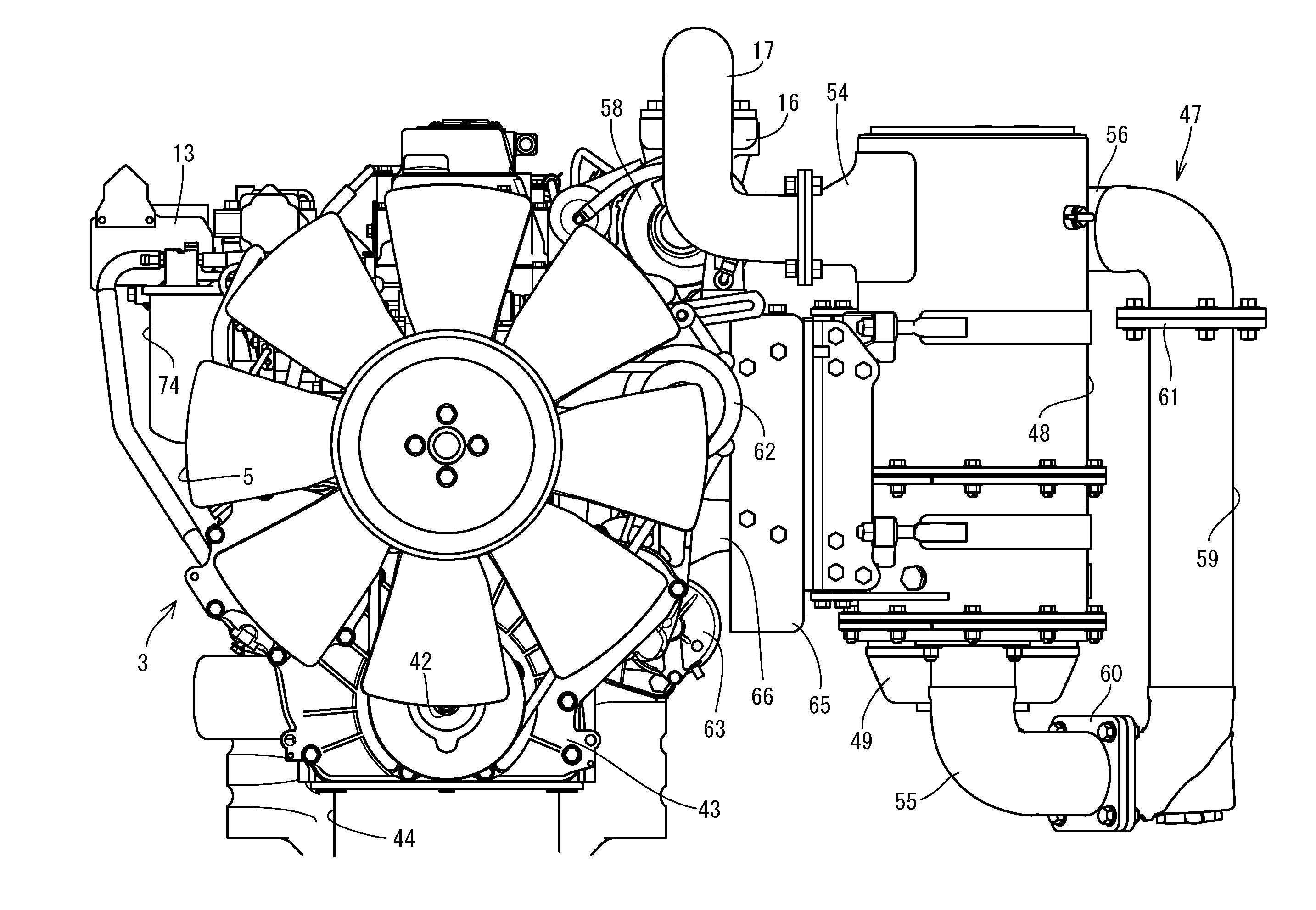
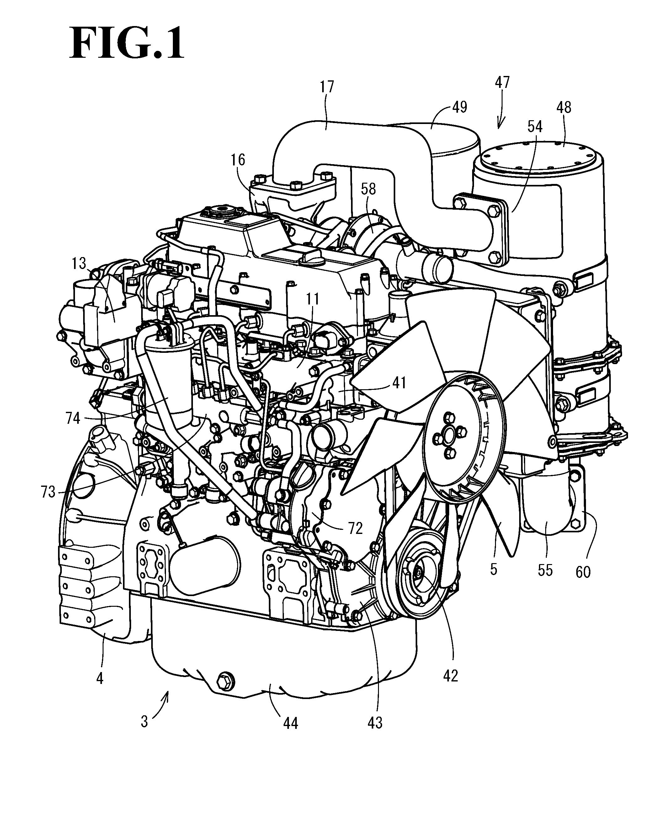
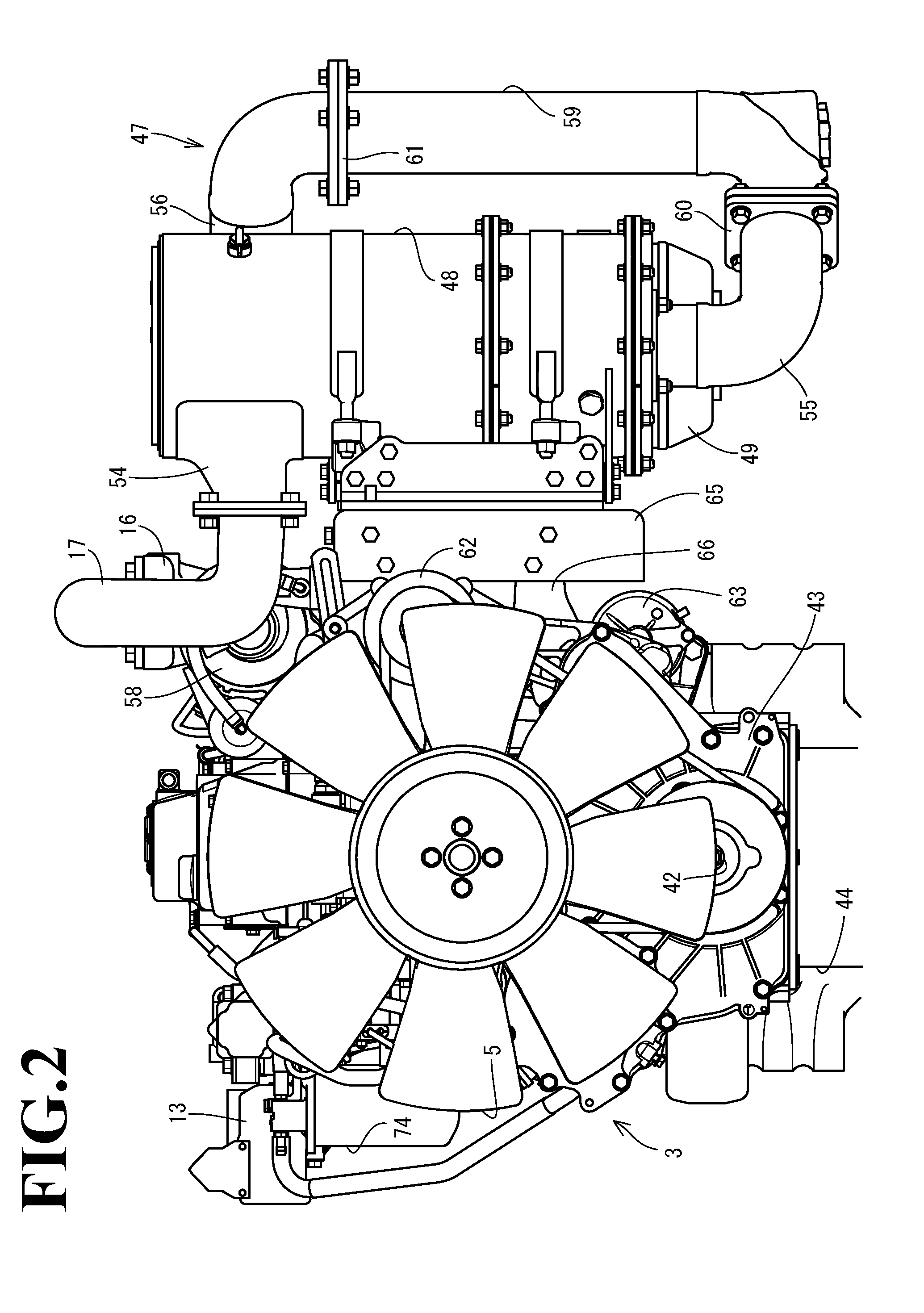
[0067]Next, the entire structure of a diesel engine 101 will be described referring to FIGS. 12 to 17. It is noted that, in the description below, the installation side of the intake manifold of the diesel engine 101 is merely referred to as “right side” of the diesel engine 101, and similarly the installation side of the exhaust manifold of the diesel engine 101 is merely referred to as “left side” of the diesel engine 101.

[0068]As illustrated in FIGS. 14 to 16, an intake manifold 103 is arranged on the right side surface of a cylinder head 102 of the diesel engine 101. The cylinder head 102 is mounted on a cylinder block 105 in which an engine output shaft 104 (crankshaft) and pistons (not illustrated) are incorporated. An exhaust manifold 106 is arranged on the left side surface of the cylinder head 102. The front end and the rear end of the engine output shaft 104 protrude from the front surface and the rear surface of the cylinder block 105.

[0069]As illustrated in FIGS. 14 to ...


PUM


Abstract

The engine device includes a first case for removing particulate matter in the exhaust gas of the engine and a second case for removing nitride oxides in the exhaust gas of the engine. The second case is connected to the first case via a urea mixing pipe. A supporting stand with which the first case, the second case, and the urea mixing pipe are adhered in parallel is provided. The first case, the second case, and the urea mixing pipe are integrally arranged on the supporting stand, thereby forming the exhaust gas purification device having single component structure, and the exhaust gas purification device is mounted on supporting leg bodies provided on the engine.

Description

CROSS-REFERENCE TO RELATED APPLICATIONS[0001]The present application is a continuation application of International Application No. PCT / JP2015 / 58280, filed Mar. 19, 2015, which claims priority to Japanese Patent Application No. 2014-59107, filed Mar. 20, 2014 and Japanese Patent Application No. 2014-65694, filed Mar. 27, 2014. The contents of these applications are incorporated herein by reference in their entirety.BACKGROUND OF THE INVENTION[0002]The present invention of the instant application relates to an engine device.[0003]Regarding work vehicles such as a tractor and a wheel loader, an opening / closing fulcrum shaft is arranged in the rear portion of a hood for covering an engine, and the hood is rotated about the opening / closing fulcrum shaft, for the purpose of improving the efficiency of maintenance work for the engine arranged in the front of a travelling vehicle body. Also, a technology of purification treatment has been known theretofore, wherein a case (hereinafter refe...

Claims


Application Information

Patent Timeline
IPC IPC(8): F01N13/18B01D46/00F01N13/00B01D53/94F01N3/035F01N3/20
CPCF01N13/18F01N3/035F01N3/2066F01N13/009B01D2279/30B01D46/001B01D46/0027F01N2250/02F01N2610/02B01D53/9431B60K13/04E02F9/0866F01N3/02F01N3/08F01N13/1805F01N2340/04F01N2450/08F01N2470/18F01N2590/08F01N2590/10Y02T10/12
Inventor SUETOU, HIROSHI
Owner YANMAR CO LTD
Why Eureka
Try Eureka