Scanning Imaging For Encoded PSF Identification and Light Field Imaging

a scanning imaging and encoded technology, applied in the field of scanning illumination and imaging, can solve the problems of psfs that cannot be deconvolved from an extended object, limited to point source objects, etc., and achieve the effect of being easily identified and removed

Active Publication Date: 2017-02-02
UNIV OF COLORADO THE REGENTS OF
View PDF15 Cites 13 Cited by
  • Summary
  • Abstract
  • Description
  • Claims
  • Application Information

AI Technical Summary

Benefits of technology

[0015]In another embodiment of the present invention, a microscope is configured to provide scanned illumination to an extended object, while applying extended depth of field and 3D depth localization encoding to the resulting set of images. A conventional reflection (or transmission) bright field (or fluorescence, darkfield, polarizing, phase contrast or interference) microscope is configured to use laterally scanned illumination (for example by moving an array in front of the light source) to scan an extended object and also uses a specially designed phase plate for encoding images. Thus multiple encoded images are generated. These images are decoded and combined, with custom digital signal processing algorithms, to form a 3D volume rendering or animation. Each point in the specimen is illuminated separately from its neighbors, and records its distinct PSF ring diameter without any ambiguity arising from adjacent points on the object. This avoids the problem of deconvolving non-orthogonal PSFs mentioned above. Many spots on the sample are illuminated and imaged at the same time, in a single camera frame, as a small number of pixels separate the centers of each PSF ring so they can be readily differentiated. Therefore, the proposed patterned illumination array achieves the necessary separation of the ring PSFs for accurate depth localization of each cell feature while maintaining the required acquisition speed.
[0016]The result of the above scanned illumination and encoded detection methods is that the singular PSF corresponding to each position on the object is detected by itself. This allows extended objects to be analyzed by the encoding PSF camera as if each point were separate from all other points.
[0019]Another embodiment adds an optical phase plate after the scanned illumination. This optical phase plate produces an elongated illumination pattern in the z-dimension (e.g. an array of Bessel beams), thus generating extended depth of field illumination. This is similar to the array of pencil beams as shown in FIG. 8. A Bessel beam (i.e., from an axicon) is not really a pencil, but has a ‘pencil’ of high intensity in its core for a long ways (compared to the diffractive spreading of a collimated beam of similar diameter).
[0024]Similar scanning illumination systems are well established in biological microscopy, such as in confocal beam scanning or Nipkow disk confocal instruments. This invention differs in that there is no pinhole in front of the detector to eliminate the light from out-of-focus PSFs. In addition, there is no need to record a multi-focal “stack” of images in order to obtain depth information. Instead, in this invention, the full area of the encoded PSF from each point on a complex extended object is imaged sequentially onto a camera. This information is then digitally processed to retrieve depth location and visualize sharply focused features throughout the 3D volume without having to change the focus setting of the microscope.
[0025]Finally, in some implementations of engineered PSFs, (such as in pending patent application Ser. No. 13 / 829,541 filed Mar. 14, 2013 and entitled “Engineered Point Spread Function for Simultaneous Extended Depth of Field and 3D Ranging”, incorporated herein by reference), each scanned encoded PSF may contain all of the information needed to reconstruct a sharp image of each feature of the original object and precisely measure its position in all three dimensions. This is possible because (1) the x-y location of the illuminated point in the object can be obtained to nano-precision accuracy (using currently available scanning mechanisms), (2) the z-location of the illuminated object point can be precisely determined by the diameter of the PSF ring image (or other shape or size or orientation change dependent of focal depth), and (3) the relative brightness of the object feature can be determined from the average intensity of the PSF image. Furthermore, most noise artifacts that are common problems in microscope imaging can be readily identified and removed from the PSF image due to their not having the characteristic ring shape of the encoded signal PSF.

Problems solved by technology

All prior art methods of PSF encoding for depth information result in PSFs that cannot be deconvolved from an extended object because they are not orthogonal.
Therefore, they are limited to point source objects that that are a very small subset of microscopy applications.

Method used


Image

  • Scanning Imaging For Encoded PSF Identification and Light Field Imaging
  • Scanning Imaging For Encoded PSF Identification and Light Field Imaging
  • Scanning Imaging For Encoded PSF Identification and Light Field Imaging

Examples


Embodiment Construction

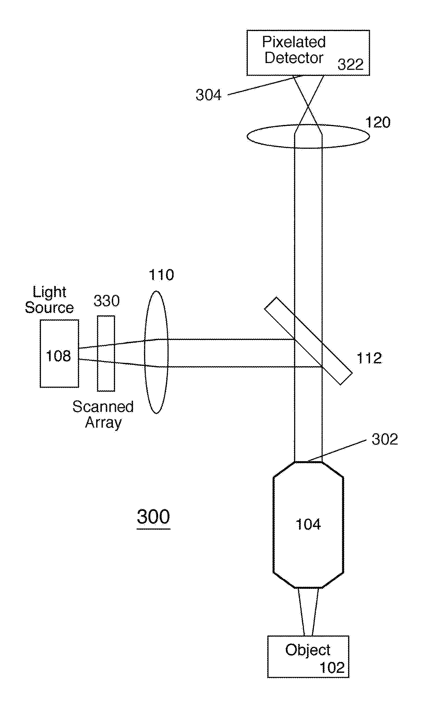
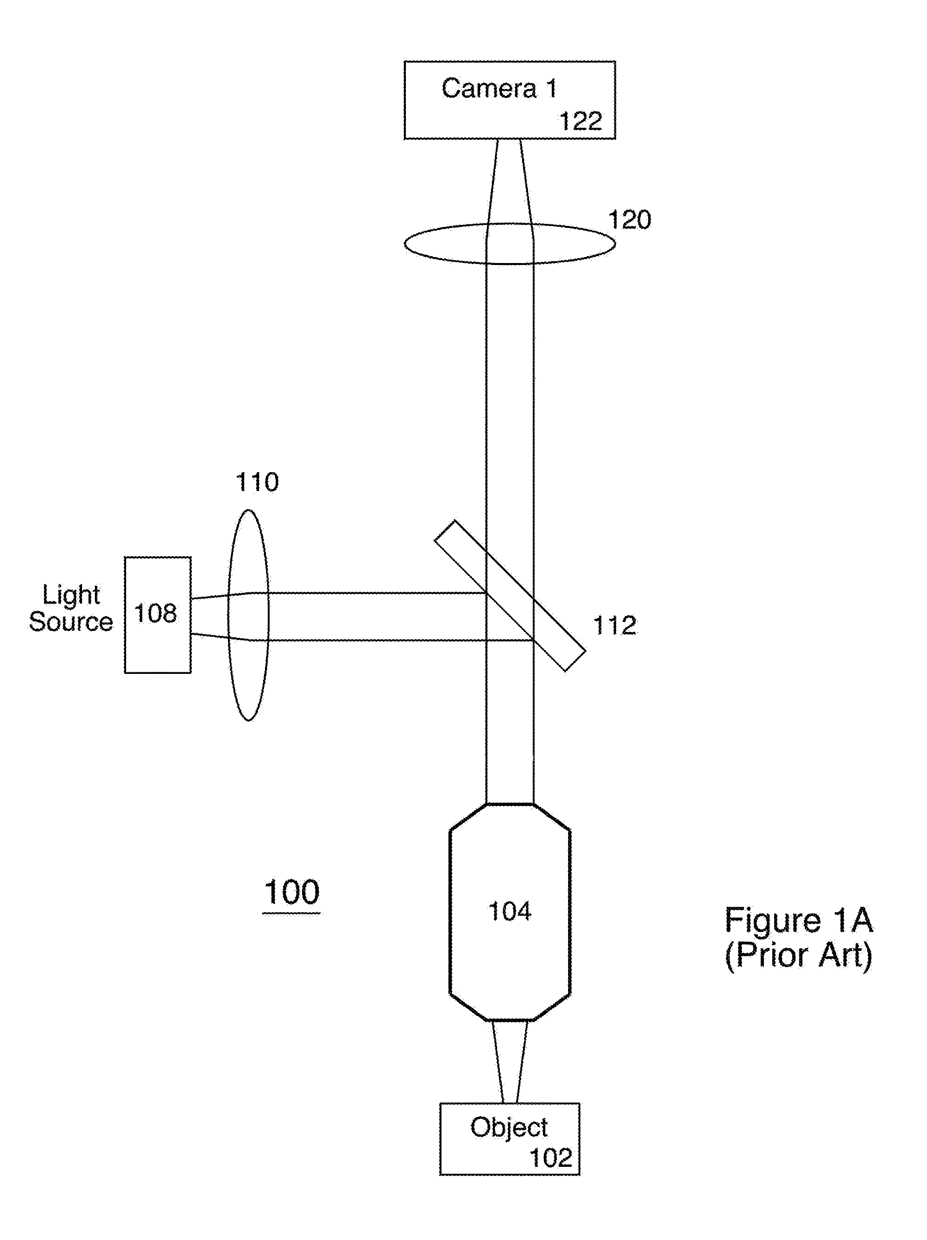
[0038]FIG. 1A (Prior Art) is a schematic block diagram illustrating a conventional reflection bright field microscope 100. Object 102 (e.g. a sample containing elements at various depths) is imaged by camera 122 and / or viewed by a user (not shown). Illumination is provided by light source 108. Optical elements include objective lens 104, lenses 110 and 120, and beam splitter 112. Conventional microscopes are capable of discerning tiny objects, but objects are only in focus over a very narrow depth of field.

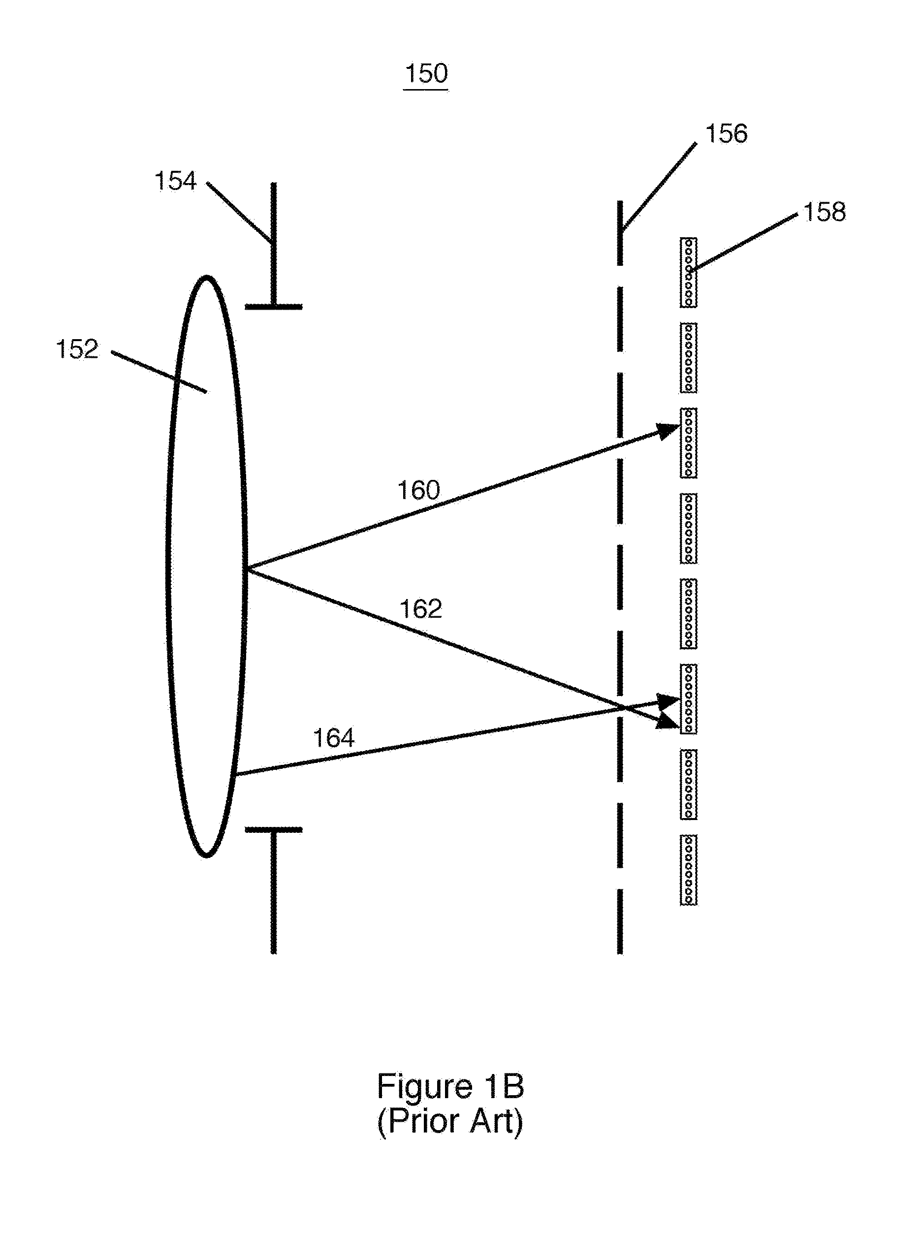
[0039]FIG. 1B (Prior Art) is a schematic block diagram illustrating a conventional Light Field imaging system 150 with a pinhole array 156 between lens 152 and pixel array 158. Aperture 154 forms the exit pupil of lens 152. Because of pinhole array 156, a specific pixel within pixel array 158 can be labeled in both position on the exit pupil and direction of ray travel. Rays 160 and 162 come from the same point on the exit pupil, but arrive at different pixels in pixel array 158. ...


PUM


Abstract

Scanned illumination allows for capturing 3-dimensional information about an object. A conventional reflection (or transmission) bright field (or fluorescence, darkfield, polarizing, phase contrast or interference) microscope is configured to use laterally scanned illumination (for example by moving an array in front of the light source) to scan an extended object. A pixelated detector may capture a series of images at the exit pupil of a microscope objective, and this series of images may be processed to form a Light Field image of the object. Or, a microscope is configured to provide scanned illumination to an extended object, while applying extended depth of field and 3D depth localization encoding to the resulting set of images. Thus multiple encoded images are generated. These images are decoded and combined, with custom digital signal processing algorithms, to form a 3D volume rendering or animation. Each point in the specimen is illuminated separately from its neighbors, and records its distinct PSF signature without any ambiguity arising from adjacent points on the object.

Description

BACKGROUND OF THE INVENTION[0001]Field of the Invention[0002]The present invention relates to scanned illumination and imaging. In particular, the present invention utilizes a microscope with scanned illumination for encoded PSF identification to accomplish depth map 3D imaging of extended objects, or for Light Field imaging of complex objects.[0003]Discussion of Related Art[0004]Existing 3D microscope technologies have limitations. Simply stated, all microscope designs are driven by the fundamental laws of physics, and specifically designed to address the tradeoffs that arise when designing lenses for high-resolution imaging. A short description of these optical tradeoffs and examples of microscope technologies that have been developed to overcome them are as follows:[0005](1) High numerical aperture (NA) objectives have a very shallow depth of field (DOF) which results in biological features outside the best focus plane appearing blurred. Confocal and widefield deconvolution micro...

Claims


Application Information

Patent Timeline
Patent Type & Authority Applications(United States)
IPC IPC(8): G02B21/36H04N5/225G02B21/00H04N13/02
CPCG02B21/367G02B21/008H04N5/2256H04N13/0271H04N13/218H04N13/271H04N23/56
Inventor COGSWELL, CAROL J.CORMACK, ROBERT H.
Owner UNIV OF COLORADO THE REGENTS OF
Why Eureka
Try Eureka