

Power transmission apparatus and power reception apparatus
a technology of power transmission apparatus and power reception coil, which is applied in the direction of charging stations, cores/yokes, transportation and packaging, etc., can solve the problems of suppressing the large variation of the coupling coefficient and the excessive increase of the amount of the magnetic flux passing through the power transmission coil. , to achieve the effect of suppressing the large variation of the coupling coefficient and large variation of the magnetic flux penetrating
- Summary
- Abstract
- Description
- Claims
- Application Information
AI Technical Summary
Benefits of technology
Problems solved by technology
Method used
Image

Examples
first embodiment
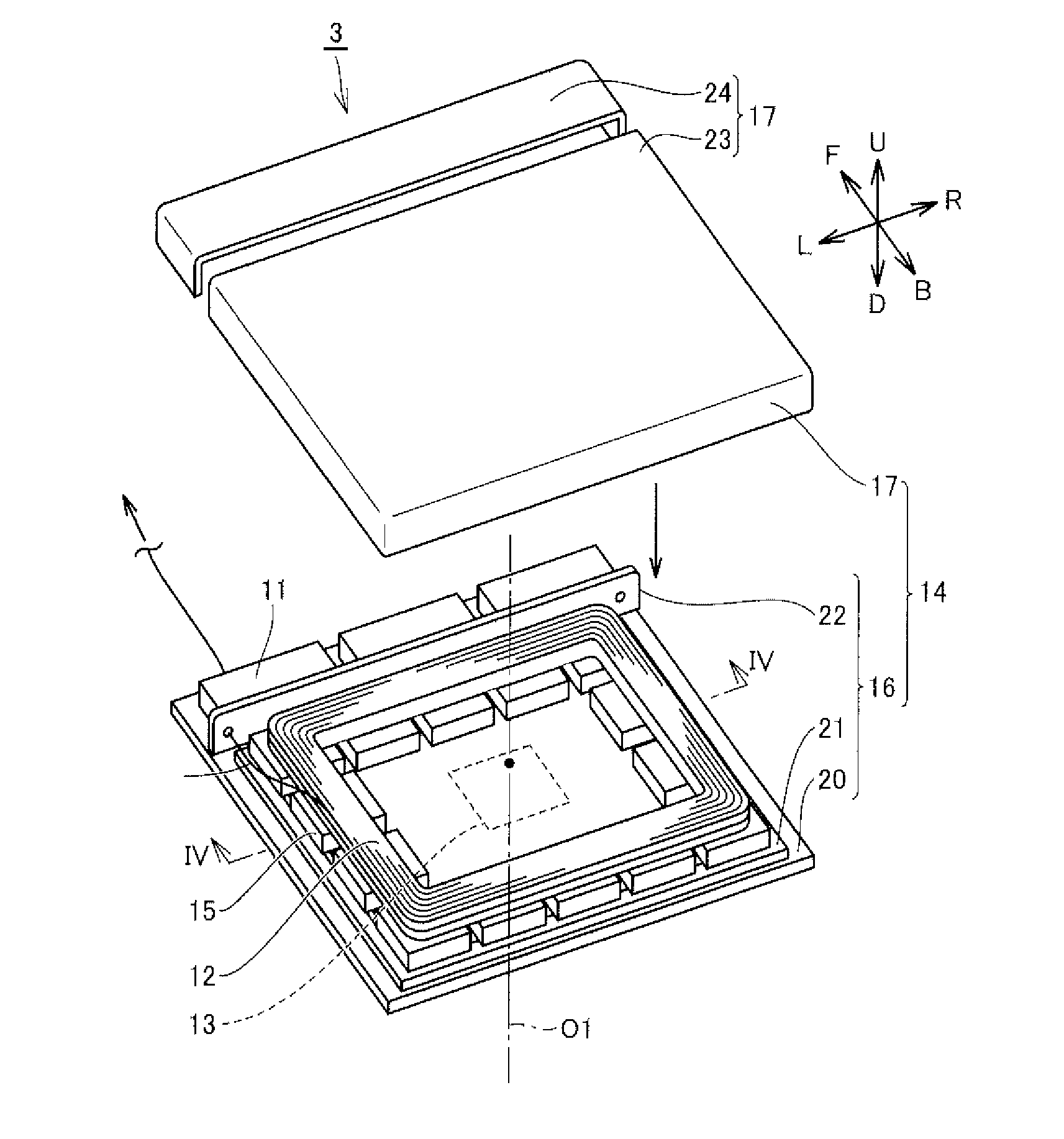
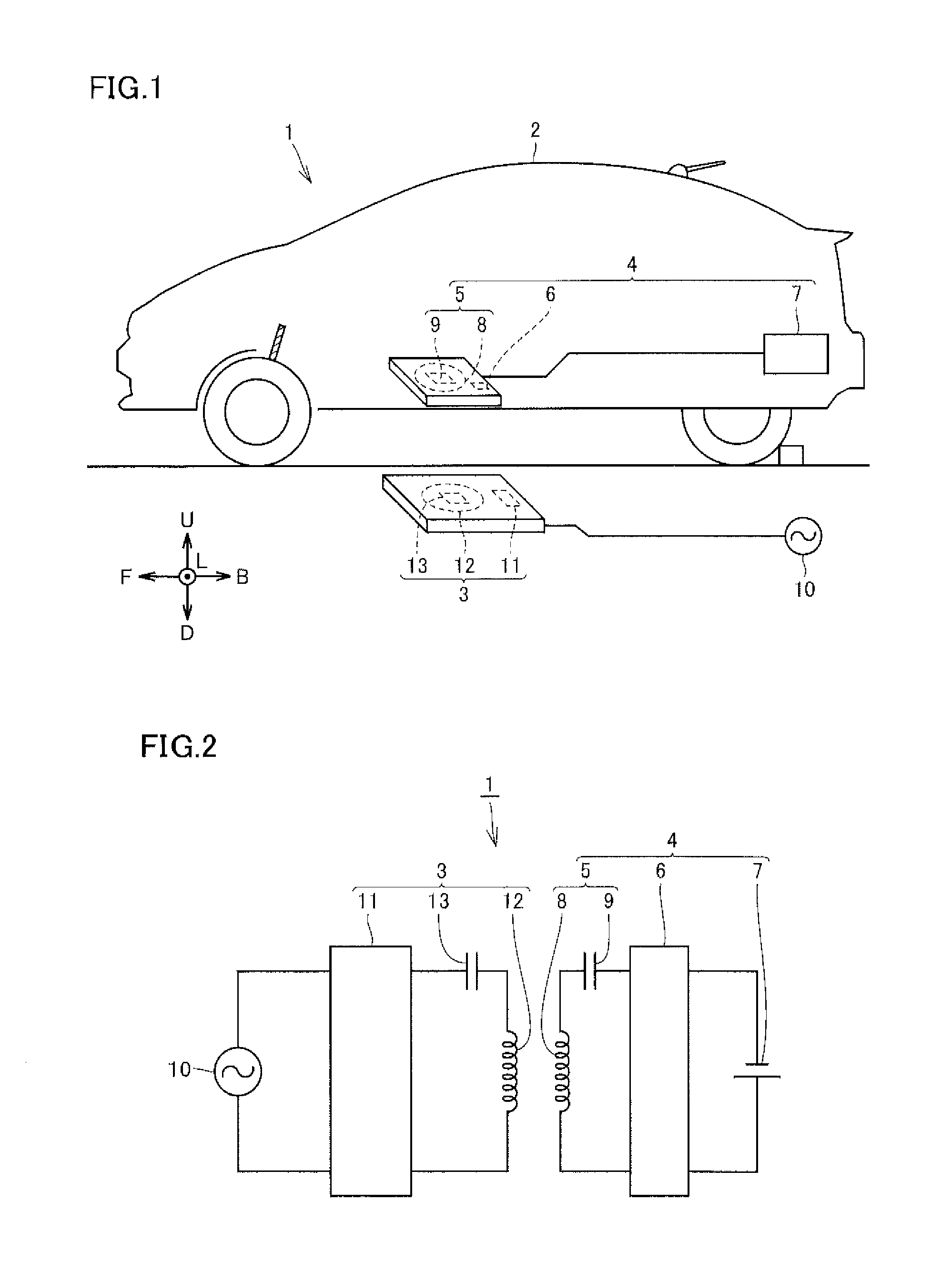
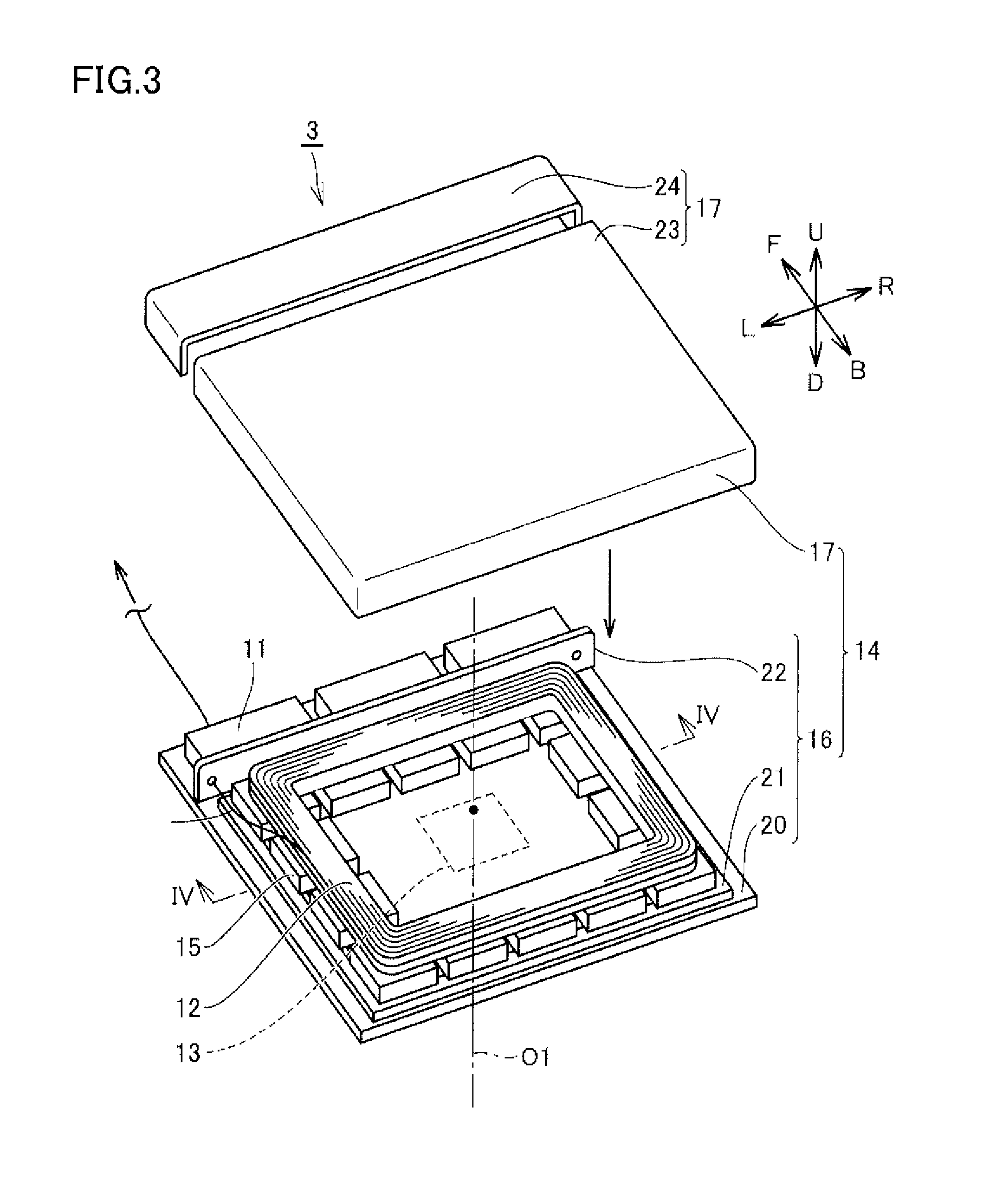
[0071]FIG. 1 is a schematic diagram schematically showing a wireless charging system 1, and FIG. 2 is a circuit diagram schematically showing wireless charging system 1. As shown in FIGS. 1 and 2, wireless charging system 1 includes a power reception unit 4 mounted on a vehicle 2, and a power transmission apparatus 3 for wirelessly transmitting electric power to power reception unit 4.
[0072]Power reception unit 4 includes a power reception apparatus 5 for receiving the electric power transmitted from power transmission apparatus 3, a rectifier 6 for converting the alternating-current (AC) power received by power reception apparatus 5 into direct-current (DC) power and adjusting the voltage, and a battery 7 for storing the DC power supplied from rectifier 6.
[0073]The electric power stored in battery 7 is supplied to a not-shown driving motor or the like, which drives the wheels of the vehicle 2.
[0074]Power reception apparatus 5 includes a power reception coil 8 and a capacitor 9 conn...
second embodiment
[0172]Referring to FIG. 21 and the like, power transmission apparatus 3 and power reception apparatus 5 according to a second embodiment are described. Any feature shown in FIG. 21 and the like identical or substantially identical to the corresponding one shown in FIGS. 1 to 20 described above is denoted by the same reference character, and the description thereof may not be repeated.
[0173]FIG. 21 is a perspective view showing power transmission apparatus 3 according to the second embodiment. As shown in FIG. 21, housing case 16 includes base plate 20, and housing portion 21 formed on the upper surface of base plate 20. A protruding portion 55 is formed in housing portion 21.
[0174]FIG. 22 is a cross-sectional view along a line XXII-XXII shown in FIG. 21. As shown in FIG. 22, housing portion 21 includes a flat portion 57 having an upper surface on which ferrite core 15 is disposed, protruding portion 55 formed in a central region of flat portion 57 and protruding upward, and a plural...
third embodiment
[0197]In the first and second embodiments described above, variation of the coupling coefficient is suppressed by reflecting the magnetic flux entering the hollow in each coil. The method of suppressing variation of the coupling coefficient is not limited to the above-described approach.
[0198]Referring to FIG. 27 and the like, a power transmission apparatus and a power reception apparatus according to the third embodiment is described. Any feature identical or substantially identical to the corresponding one shown in FIGS. 21 to 26 described above is denoted by the same reference character, and the description thereof may not be repeated.
[0199]FIG. 27 is a cross-sectional view showing power reception apparatus 5 according to the third embodiment. As shown in FIG. 27, power reception apparatus 5 includes a magnetic sheet 80 disposed on the lower surface of flat portion 46 which is exposed at opening 51.
[0200]Magnetic sheet 80 includes an adhesive layer 81 adhered to the lower surface...
PUM
| Property | Measurement | Unit |
|---|---|---|
| width | aaaaa | aaaaa |
| resistance | aaaaa | aaaaa |
| magnetic resistance | aaaaa | aaaaa |
Abstract
Description
Claims
Application Information