Micromechanical frequency divider

a frequency divider and micro-mechanical technology, applied in the field of frequency dividers, can solve the problems of unfriendly 120 mw consumption of commercial csacs, and achieve the effects of consuming almost negligible power, high frequency operation, and minimal noise of divided signals

Active Publication Date: 2017-02-16
RGT UNIV OF CALIFORNIA
View PDF2 Cites 12 Cited by
  • Summary
  • Abstract
  • Description
  • Claims
  • Application Information

AI Technical Summary

Benefits of technology

[0011]Accordingly, a need exists for frequency division devices which can operate with low power consumption at high frequencies in the MHz to GHz range while adding minimal noise to the divided signal. The technology presented provides high frequency operation at meager power levels while overcoming other shortcomings of previous solutions.
[0012]A method and apparatus are disclosed for realizing frequency division through utilizing a parametric amplification effect in a capacitive-gap (or capacitive coupling or capacitive transducer) transduced micromechanical resonator while consuming almost negligible power. In actual demonstration, a divide-by-two version of this frequency divider provides not only the 6 dB reduction in close-to-carrier phase noise expected for a frequency divide-by-two function, but also beneficially provides a 23 dB reduction in far-from-carrier noise due to filtering by its extremely high mechanical Q of 91,500. The parametric oscillator frequency divider works in response to modulation of a frequency-determining parameter of a resonator, e.g., electrical stiffness, at twice the resonance frequency of the mechanical resonator. This produces an effect analogous to a child on a swing, where swinging legs modulate frequency (or stiffness), providing gain and enhancement of in-phase resonant motion. When driven with sufficient pump strength, this gain overcomes resonator losses and amplifies the (initially Brownian) motion into steady-state oscillation at the fundamental resonator frequency.
[0013]The demonstrated embodiments include micromechanical resonators used singly and in array configurations. The resonators utilize tiny electrode-to-disk gaps that accentuate electrical stiffness nonlinearity for parametric excitation. The divider requires no active devices and thus adds no noise to the signal. Additionally, with power consumption in principle limited only by MEMS resonator loss, power usage is essentially zero (e.g., 25 nW), offering a compelling alternative to much more power hungry digital electronic dividers. The mechanical frequency dividers as described herein are expected to enable exceptionally low-power frequency synthesizers for applications where the operating frequency remains within the tuning range of the MEMS resonator, such as Chip-Scale Atomic Clock (CSAC). Indeed, commercial CSACs presently consume a battery-unfriendly 120 mW, with a substantial portion of this power being utilized by the frequency dividers in their synthesizers. A mechanical frequency divider consuming only 25 nW or less would greatly reduce power consumption, increasing the application range of CSAC to include an enormous number of applications involving mobile devices.
[0014]This present disclosure practically eliminates power consumption when performing frequency division, which can lead to greatly lowered power usage for nearly all synchronous electronic devices which require a clock. This includes applications as common-place as cell phones, televisions, and computers; to exotic applications such as chip-scale atomic clocks and gyroscopes.

Problems solved by technology

Indeed, commercial CSACs presently consume a battery-unfriendly 120 mW, with a substantial portion of this power being utilized by the frequency dividers in their synthesizers.

Method used


Image

  • Micromechanical frequency divider
  • Micromechanical frequency divider
  • Micromechanical frequency divider

Examples


Embodiment Construction

[0035]1. Introduction

[0036]The disclosure presents a frequency divider using a parametric amplification effect in a capacitive-gap / coupling / transducer transduced micro-electromechanical system (MEMS) device.

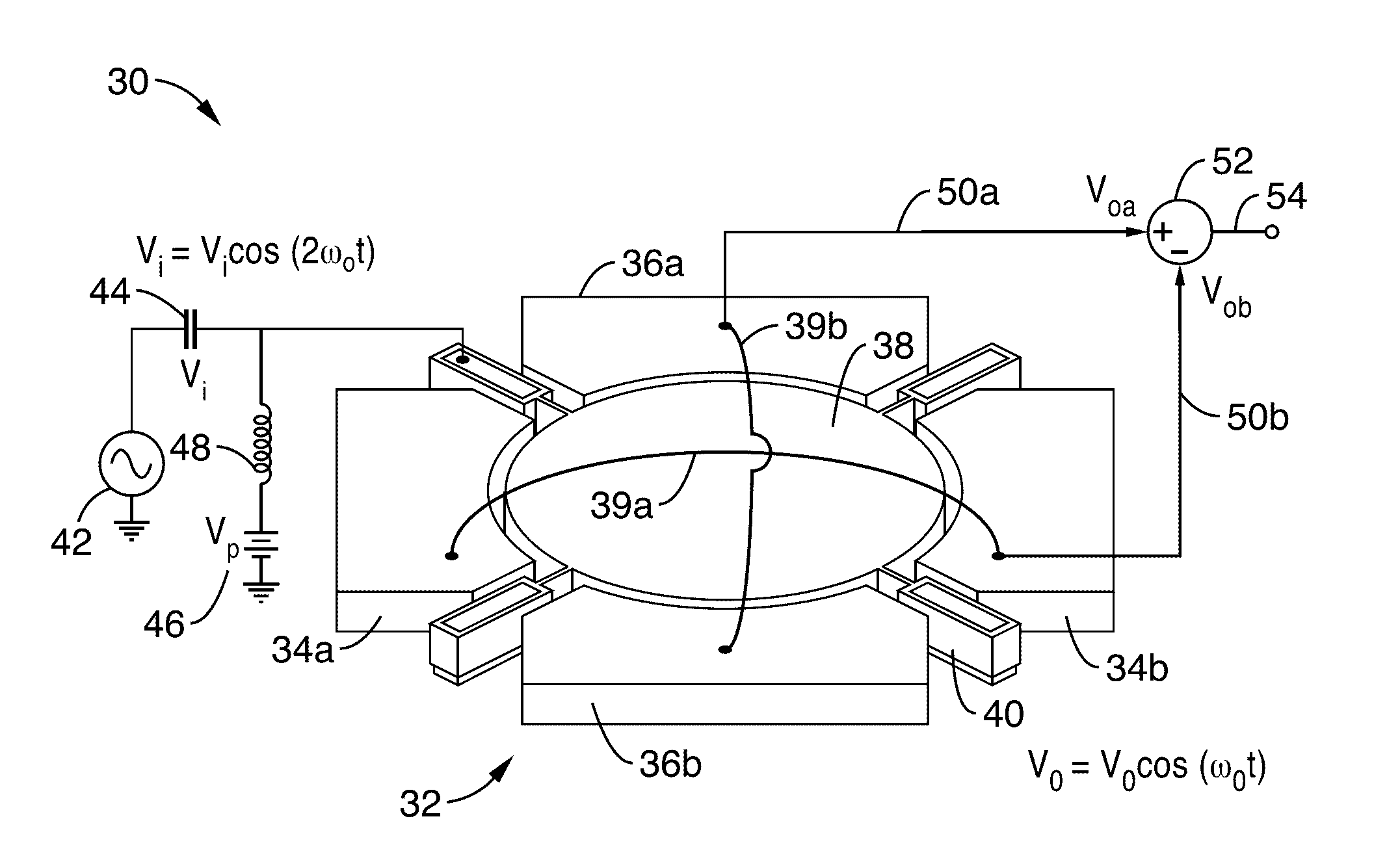
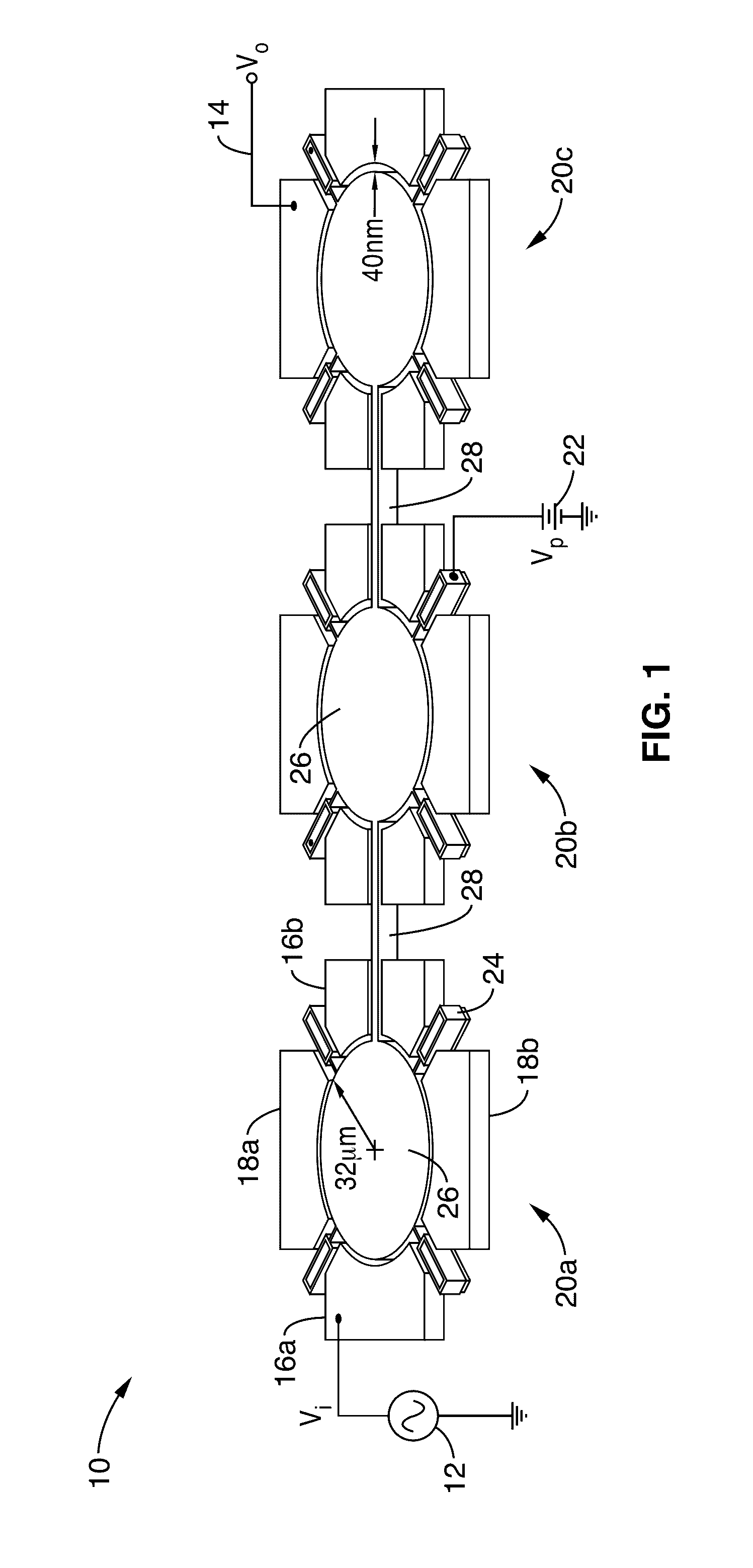
[0037]FIG. 1 illustrates an example embodiment 10 of a parametric divider showing 121-MHz pump signal vi 12 applied to the input electrodes and resultant 60.6-MHz signal on the output electrodes vo 14. By way of example and not limitation, the resonator structure utilized in this parametric divider comprises an array of wine-glass disks resonators. Each disk structure has input electrodes 16a, 16b, and output electrodes 18a, 18b. It should be appreciated that a typical embodiment includes electrical inter-connection of electrodes disposed on opposing sides of the resonator, such as connecting 16a to 16b, and 18a to 18b. However, it should also be noted that more general connection topologies may be utilized without departing from the teachings of this disclosure.

[0038]The disk ar...


PUM


Abstract

A micro-electromechanical system (MEMS) frequency divider apparatus having one or more MEMS resonators on a substrate is presented. A first oscillator frequency, as an approximate multiple of the parametric oscillation frequency, is capacitively coupled from a very closely-spaced electrode (e.g., 40 nm) to a resonant structure of the first oscillator, thus inducing mechanical oscillation. This mechanical oscillation can be coupled through additional MEMS resonators on the substrate. The mechanical resonance is then converted, in at least one of the MEMS resonators, by capacitive coupling back to an electrical signal which is a division of the first oscillation frequency. Output may be generated as a single ended output, or in response to a differential signal between two output electrodes.

Description

CROSS-REFERENCE TO RELATED APPLICATIONS[0001]This application is a 35 U.S.C. §111(a) continuation of PCT international application number PCT / US2014 / 068209 filed on Dec. 2, 2014, incorporated herein by reference in its entirety, which claims priority to, and the benefit of, U.S. provisional patent application Ser. No. 61 / 910,916 filed on Dec. 2, 2013, incorporated herein by reference in its entirety. Priority is claimed to each of the foregoing applications.[0002]The above-referenced PCT international application was published as PCT International Publication No. WO 2015 / 126498 on Aug. 27, 2015, which publication is incorporated herein by reference in its entirety.STATEMENT REGARDING FEDERALLY SPONSORED RESEARCH OR DEVELOPMENT[0003]This present disclosure was made with Government support under 29944-23803-44, awarded by the U.S. Government Defense Advanced Research Projects Agency (DARPA). The Government has certain rights in the invention.INCORPORATION-BY-REFERENCE OF COMPUTER PROG...

Claims


Application Information

Patent Timeline
Patent Type & Authority Applications(United States)
IPC IPC(8): H03B19/14H03H9/25H03H9/02H03H9/17H03H9/24H03L7/18
CPCH03B19/14H03H9/2436H03L7/18H03H9/2431H03B2200/0016H03H9/02007H03H9/171H03H9/25H03H9/2447H03B19/00H03K25/02
Inventor NGUYEN, CLARK T.-C.ROCHELEAU, TRISTAN O.
Owner RGT UNIV OF CALIFORNIA
Why Eureka
Try Eureka