
Intracerebral current simulation method and device thereof, and transcranial magnetic stimulation system including intracerebral current simulation device

a transcranial magnetic stimulation and simulation method technology, applied in the field of intracerebral current simulation method and device thereof, and the simulation device of the transcranial magnetic stimulation system including the intracerebral current, can solve the problems of craniotomy, which is often not desired by patients, and the drug therapy may not be effective in these diseases, so as to achieve the effect of simplifying the calculation

Inactive Publication Date: 2017-02-23
THE UNIV OF TOKYO +1
View PDF1 Cites 6 Cited by
  • Summary
  • Abstract
  • Description
  • Claims
  • Application Information

AI Technical Summary

Benefits of technology

The patent describes a method for conducting studies and treatments on the brain using magnetic stimulation. The method uses a software program called SPFD, which allows for more efficient and accurate analysis and treatment compared to traditional methods. The software program can create models of the brain and analyze them to determine the optimal position for stimulation. This analysis can help design a more efficient transcranial magnetic stimulation system. Overall, the method can save time and improve the effectiveness of brain treatment.

Problems solved by technology

A drug therapy may not effective to these diseases in some cases and methods of treatment in such a case include applying an electrical stimulation to the brain by implanting an electrode into the brain.
However, this method requires a craniotomy and is therefore often not desired by patients.
However, a conventional magnetic stimulation device weighs about 70 Kg and is available only in well-equipped medical institutions because electrical work is required for installation.

Method used


Image

  • Intracerebral current simulation method and device thereof, and transcranial magnetic stimulation system including intracerebral current simulation device
  • Intracerebral current simulation method and device thereof, and transcranial magnetic stimulation system including intracerebral current simulation device
  • Intracerebral current simulation method and device thereof, and transcranial magnetic stimulation system including intracerebral current simulation device

Examples


first embodiment

[0121]Referring to FIG. 16, a transcranial magnetic stimulation system (hereinafter simply referred to as the “system”) 1 has a magnetic stimulation device 4 applying a magnetic stimulation to the brain of a patient 3 supported by a support mechanism (e.g., a chair 2 or a bed).

[0122]The magnetic stimulation device 4 has a coil unit (coil device) 5 and a control unit 6 so as to form a dynamic magnetic field applying the magnetic stimulation to the brain of the patient 3.

[0123]As shown, the coil unit 5 is preferably supported by a proper positioning unit 7 to enable free movement along a head surface of the patient 3 and positioning at an arbitrary position. The coil unit 5 includes the coil 8 and a casing 9 made of an electrical insulating material surrounding the coil 8. The casing 9 includes a holder 10 formed integrally with the casing 9 and is held via the holder 10 by the positioning unit 7. The coil 8 can be any known coil such as one cyclic coil and a figure-eight coil having ...


PUM


Abstract

An intracerebral current simulation method including a first step of providing head image data; a second step of forming a three-dimensional brain model including micro-polyhedron units; a third step of providing first information which includes conditions under which a coil is placed on a patient's head, an electric current is applied to the coil, and the patient's reaction to the magnetic stimulation is observed, the conditions including a position and orientation of the coil, an electric current applied to the coil, and a structure relating to a generated magnetic field of the coil; and a fourth step of calculating an eddy current or electric field induced inside each of the micro-polyhedron units on the basis of the first information provided in the third step and second information which includes conductivity assigned to each micro-polyhedron unit. Also disclosed is a transcranial magnetic stimulation device and system.

Description

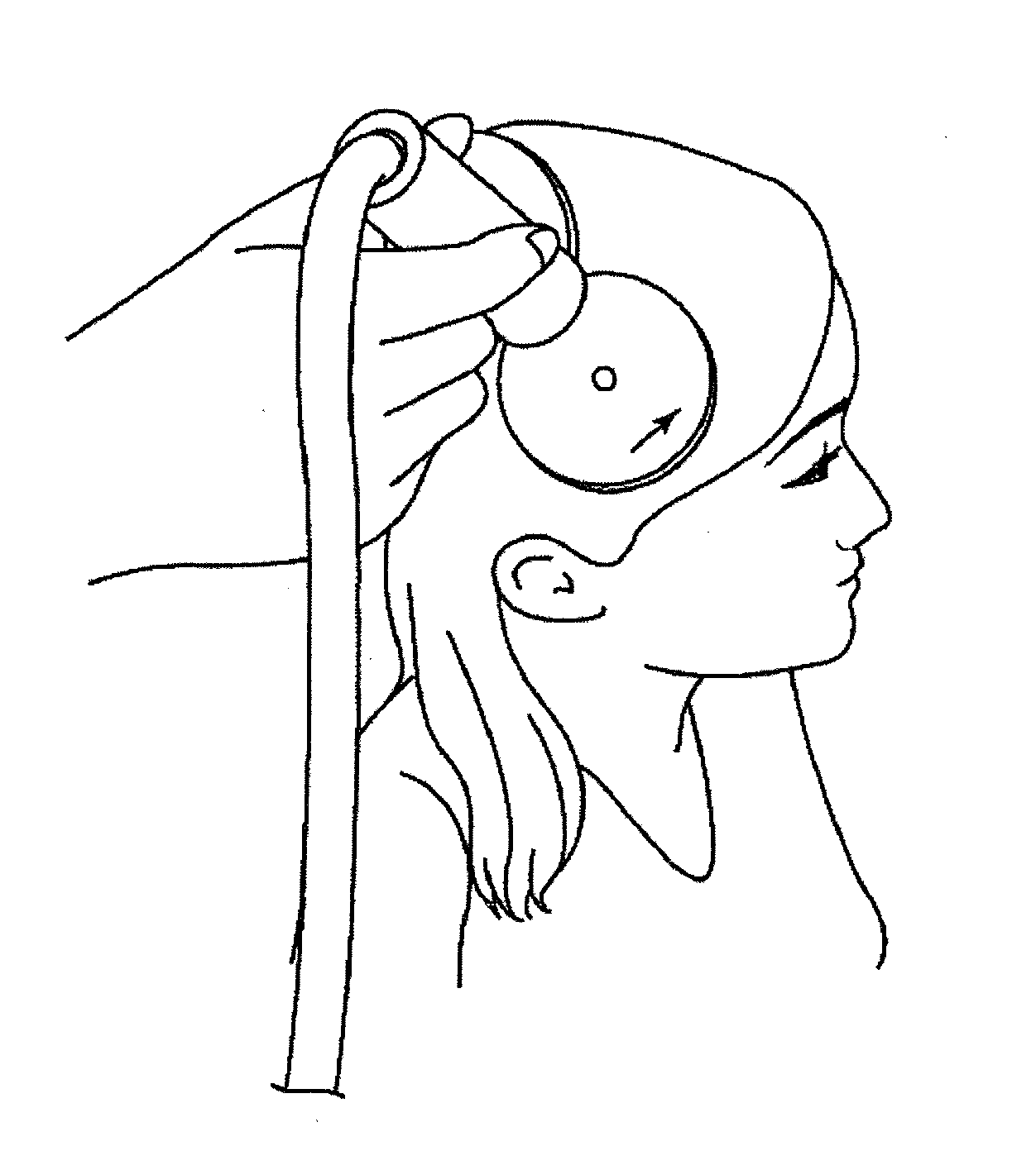
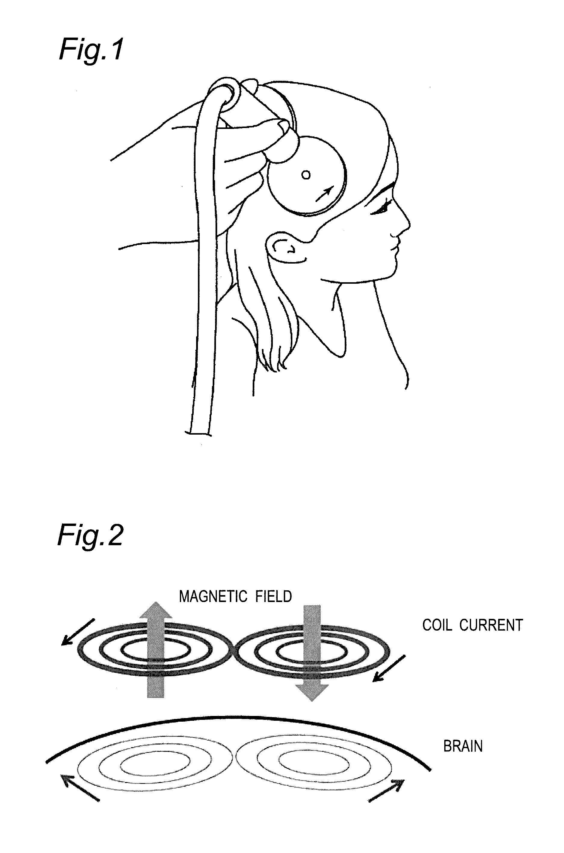
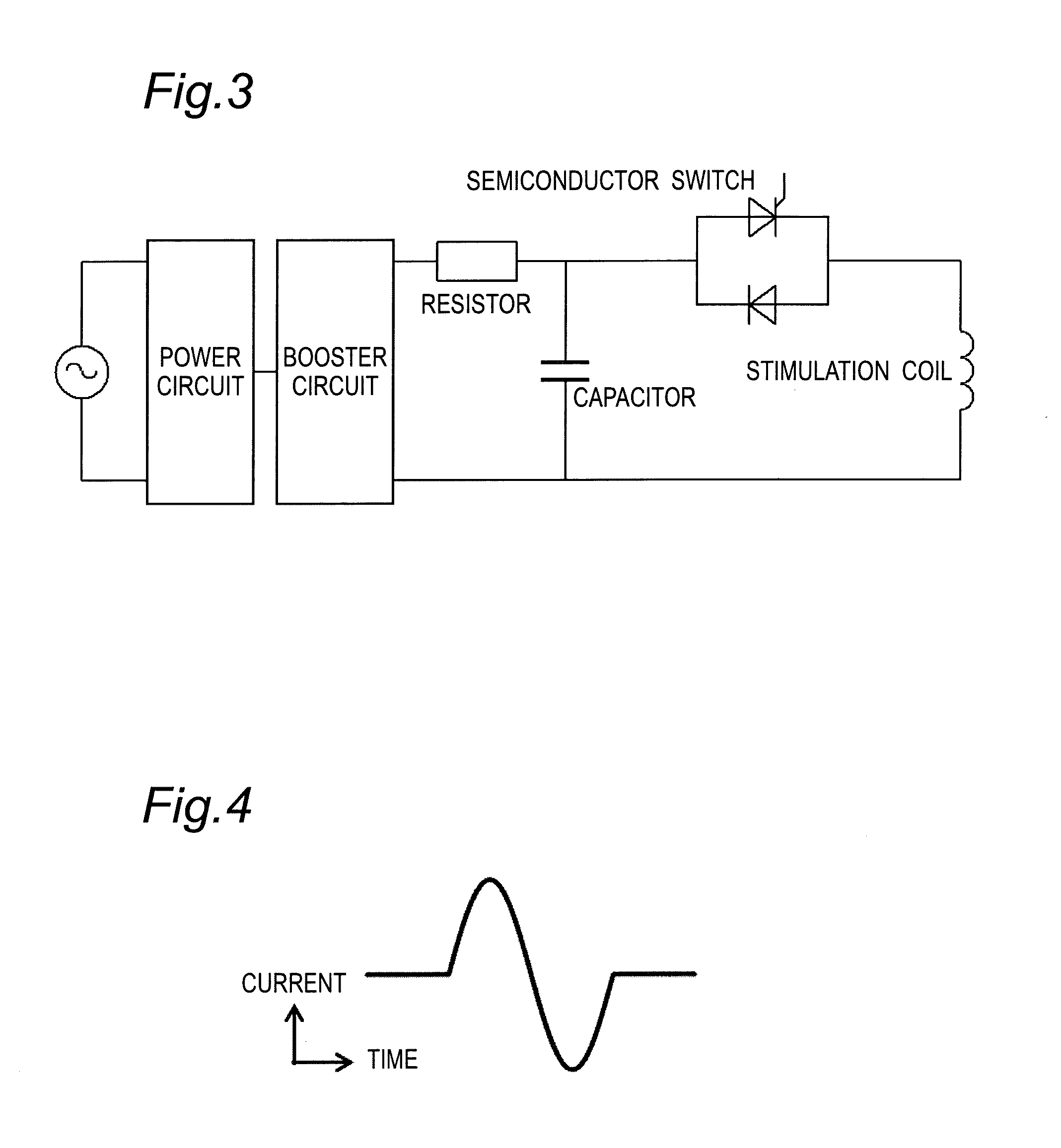
TECHNICAL FIELD[0001]The present invention relates to a method and a device for simulating an electric current or an electric field induced into the brain. The present invention also relates to a transcranial magnetic stimulation system having the device incorporated therein.BACKGROUND ART[0002]A transcranial magnetic stimulation is a technique of stimulating neurons by inducing an eddy current or an electric field in the brain through electromagnetic induction. In this technique, as shown in FIGS. 1 and 2, a current (e.g., alternating current) is applied to a stimulation coil placed on the skin of the head to form a variable magnetic field and to induce an eddy current or an electric field in the direction opposite to the coil current in the brain under the effect of the variable magnetic field, and an action potential is generated by stimulating the neurons with the eddy current or the electric field.[0003]FIG. 3 shows an example of a stimulation coil drive circuit. In a principle...

Claims


Application Information

Patent Timeline
IPC IPC(8): A61B5/00A61B5/055G06T15/08A61N2/02
CPCA61B5/4848A61B5/4064A61N2/02G06T2210/41A61B5/055G06T15/08A61B5/742A61N2/006A61B34/10G16H40/63G16H20/30G16H50/50G16H30/40
Inventor SAITOH, YOUICHISEKINO, MASAKITAKIYAMA, YOSHIHIROYAMAMOTO, KEITA
Owner THE UNIV OF TOKYO
Learn More