A Wind Turbine Blade and an Associated Manufacturing Method

a technology manufacturing methods, applied in the field of wind turbine blades, to achieve the effect of improving the noise reduction or modulation of the wind turbine blade trailing edg

Active Publication Date: 2017-02-23
LM WP PATENT HLDG
View PDF1 Cites 24 Cited by
  • Summary
  • Abstract
  • Description
  • Claims
  • Application Information

AI Technical Summary

Benefits of technology

[0023]By providing a number of different fibre layers projecting from the trailing edge of the blade, the noise reduction or modulation of the wind turbine blade trailing edge can be improved, as different layers can be arranged to modulate different noise frequencies, e.g. by cutting said layers to different lengths, etc.

Problems solved by technology

However, such devices require secure attachment to the blade structure, and present challenges regarding suitable bonding techniques and acceptable distribution of loading forces.

Method used


Image

  • A Wind Turbine Blade and an Associated Manufacturing Method
  • A Wind Turbine Blade and an Associated Manufacturing Method
  • A Wind Turbine Blade and an Associated Manufacturing Method

Examples


Embodiment Construction

[0032]An embodiment of the invention will now be described, by way of example only, with reference to the accompanying drawings, in which:

[0033]FIG. 1 shows a wind turbine;

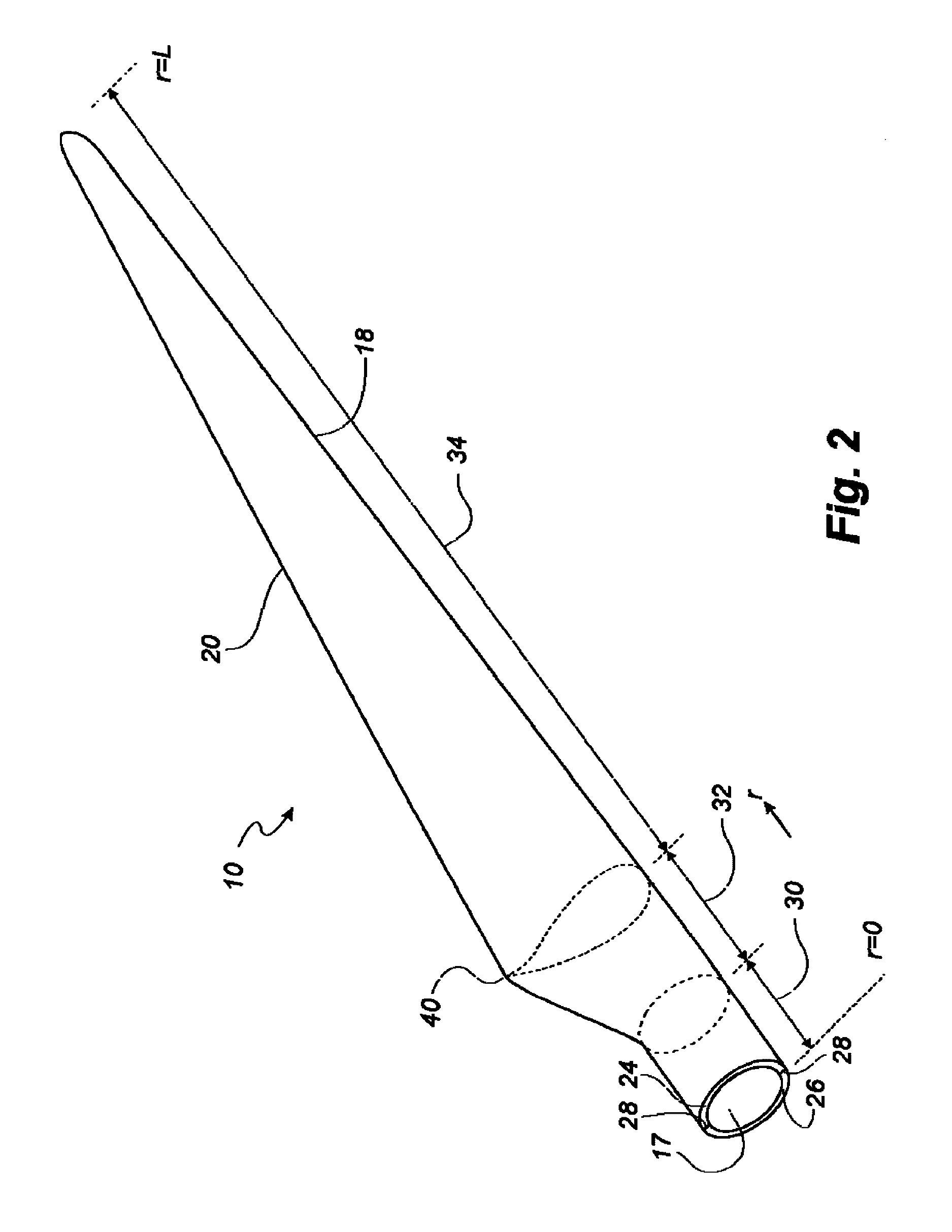
[0034]FIG. 2 shows a schematic view of a wind turbine blade according to the invention;

[0035]FIG. 3 shows a schematic view of an airfoil profile of the blade of FIG. 2;

[0036]FIG. 4 shows a schematic view of the wind turbine blade of FIG. 2, seen from above and from the side; and

[0037]FIGS. 5(a)-(c) illustrate the steps of a manufacturing method according to the invention.

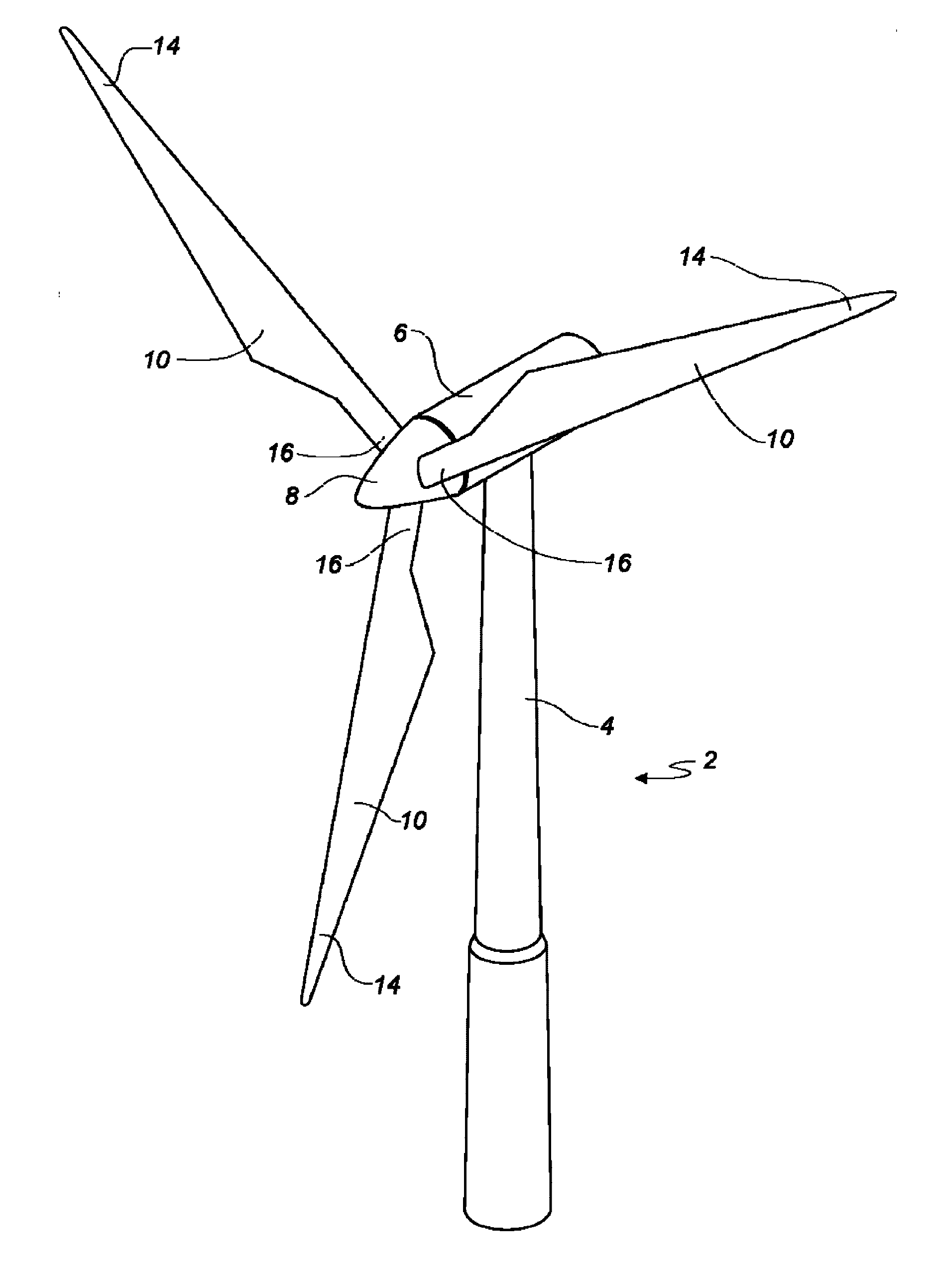
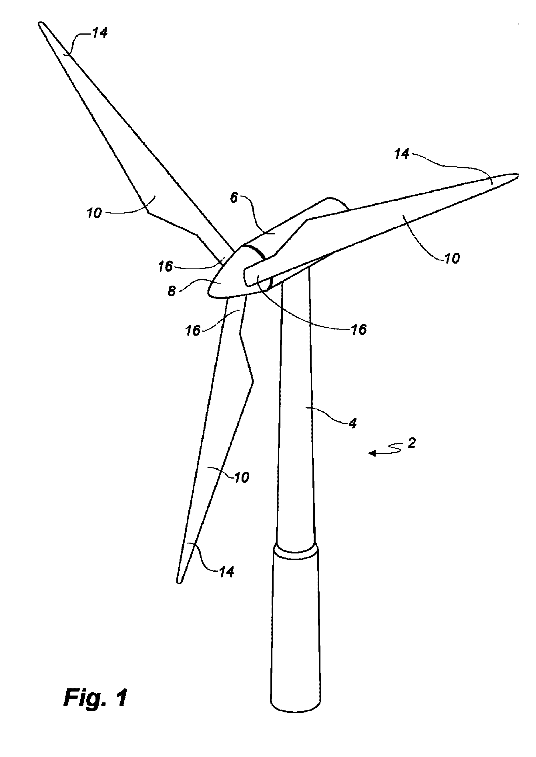
[0038]FIG. 1 illustrates a conventional modern upwind wind turbine 2 according to the so-called “Danish concept” with a tower 4, a nacelle 6 and a rotor with a substantially horizontal rotor shaft. The rotor includes a hub 8 and three blades 10 extending radially from the hub 8, each having a blade root 16 nearest the hub and a blade tip 14 furthest from the hub 8. The rotor has a radius denoted R.

[0039]FIG. 2 shows a schematic view of a wind turb...


PUM

PropertyMeasurementUnit
chord lengthaaaaaaaaaa
lengthaaaaaaaaaa

Abstract

A manufacturing method is described for a wind turbine blade, where layers of fibre material are laid up in a mould to form a portion of the blade structure. The fibre layers are infused with a resin which is subsequently cured to form the hardened blade structure. Some of the layers of fibre material are arranged so that a portion of the layers are kept resin-free during the infusion and curing steps, so that the fibre layer extends freely out from the external surface of the blade, preferably at the blade trailing edge, to provide a flexible blade trailing edge to reduce blade operational noise.

Description

FIELD OF THE INVENTION[0001]The present invention relates to a wind turbine blade having trailing edge arranged to reduce operational noise and a method of manufacturing such a wind turbine blade.BACKGROUND OF THE INVENTION[0002]Wind turbine blades are sometimes provided with trailing edge devices, in an effort to reduce the operational noise generated from the trailing edges of the blades during turbine operation. Such devices can include serrated panels or strips of bristles or flexible rods. However, such devices require secure attachment to the blade structure, and present challenges regarding suitable bonding techniques and acceptable distribution of loading forces.[0003]PCT patent application publication number WO 95 / 19500 describes how a strip of reinforced fibres may be introduced between the two shell halves of a wind turbine blade during assembly, or laminated into the trailing edge end of a shell half. The strip of reinforced fibres is then arranged as a flexible trailing...

Claims


Application Information

Patent Timeline
Patent Type & Authority Applications(United States)
IPC IPC(8): F03D1/06B29C70/44B29C70/54B29C70/34
CPCF03D1/065B29C70/34B29C70/443F05B2240/311B29L2031/085F05B2240/2211F05B2280/6003B29C70/545B29C70/54F03D1/0675B29L2031/08B29D99/0025B29C70/342B29C2793/009F05B2260/96Y02E10/72Y02P70/50
Inventor KLITGAARD, MICHAELANDERSEN, CHRISTIAN FRANKRAVN, MORTENSKOVBY, CASPERBOJESEN, SIMON BERGBAEK, PETER
Owner LM WP PATENT HLDG
Why Eureka
Try Eureka