Gas-Dissolving Device and Gas-Dissolving Method

a gas dissolving and gas technology, applied in the direction of dissolving, multi-stage water/sewage treatment, dissolving, etc., can solve the problems of excess reactive oxygen species that exist without being broken down, cell damage, etc., and achieve the effect of convenient attachment to a water server

Active Publication Date: 2017-03-09
HIKARIMIRAI
View PDF3 Cites 4 Cited by
  • Summary
  • Abstract
  • Description
  • Claims
  • Application Information

AI Technical Summary

Benefits of technology

[0032]It is therefore an object of the present invention to resolve the problems of the above-described prior art and provide a gas dissolving device that can be provided to dissolve gas in a liquid in a supersaturated state and maintain such a supersaturated state in a stable manner, and can be easily attached to a water server or the like.
[0033]As a result of intensive studies conducted to solve the problems described above, the inventors discovered that the above-described object can be achieved by providing pressure reduction and transfer means and further adjusting the pressure applied to the liquid, thus completing the present invention.
[0034]That is, a gas dissolving device of

Problems solved by technology

Nevertheless, all reactive oxygen species are not necessarily broken down by enzymes, resulting in excess reactive oxygen species that exist without being broken down.
As a result, cells are damaged by the excess

Method used


Image

  • Gas-Dissolving Device and Gas-Dissolving Method
  • Gas-Dissolving Device and Gas-Dissolving Method
  • Gas-Dissolving Device and Gas-Dissolving Method

Examples


example 1

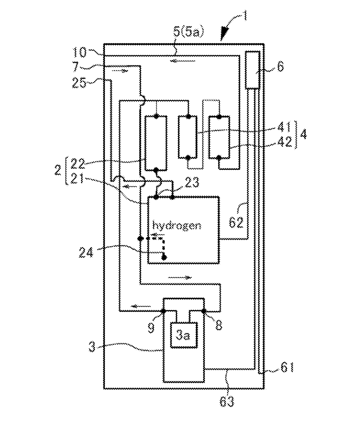
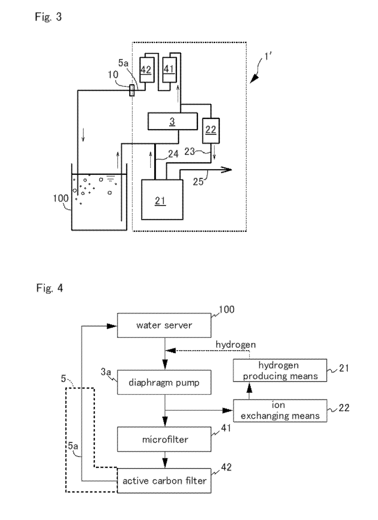
[0073]The gas dissolving device 1 illustrated in FIG. 1 was connected to the commercial water server 100 as illustrated in FIG. 3 and circulated four times to generate hydrogen water. A small tube made of polypropylene having an inside diameter of 2 mm and a length of 1.6 m was used as the small tube 5a of the pressure reduction and transfer means 5. The hydrogen water was generated using a pressure of 0.41 MPa, a hydrogen production rate of 21 cm3 / min, and a water flow rate of 730 cm3 / min. The hydrogen water had a hydrogen concentration of 6.5 ppm at 7° C. in water after 30 minutes of operation, and a supersaturated state was maintained.

example 2

[0074]The gas dissolving device 1 illustrated in FIG. 1 was connected to a water supply and circulated four times to generate hydrogen water. A small tube made of polypropylene having an inside diameter of 2 mm and a length of 1.6 m was used as the small tube 5a of the pressure reduction and transfer means 5. The hydrogen water was generated using a pressure of 0.25 MPa, a hydrogen production rate of 21 cm3 / min, and a water flow rate of 730 cm3 / min. The hydrogen water had a hydrogen concentration of 2.6 ppm at 11° C. in water after 30 minutes of operation, and a supersaturated state was maintained.

example 3

[0075]The gas dissolving device 1 illustrated in FIG. 1 was connected to the commercial water server 100 as illustrated in FIG. 3 and circulated four times to generate hydrogen water. A small tube made of polypropylene having an inside diameter of 2 mm and a length of 1.6 m was used as the small tube 5a of the pressure reduction and transfer means 5. The hydrogen water was generated using a pressure of 0.30 MPa, a hydrogen production rate of 21 cm3 / min, and a water flow rate of 730 cm3 / min. The hydrogen water had a hydrogen concentration of 5.9 ppm at 7° C. in water after 30 minutes of operation, and a supersaturated state was maintained.


PUM

PropertyMeasurementUnit
Diameteraaaaaaaaaa
Pressureaaaaaaaaaa
Diameteraaaaaaaaaa

Abstract

Provided is a gas dissolving device capable of dissolving gas in a liquid in a supersaturated state and maintaining such a saturated state in a stable manner, and being easily attached to a water server or the like.
The gas dissolving device generates hydrogen water by dissolving hydrogen in water, and discharges the hydrogen water from an outlet. The gas dissolving device includes a dissolving chamber that stores under pressure generated hydrogen water introduced therein, and pressure reduction and transfer means for preventing pressure variation in a tube-shaped passage that connects the dissolving tank and the outlet due to an action of discharging the hydrogen water from the outlet, and for forming a laminar flow.

Description

BACKGROUND OF THE INVENTION[0001]Field of the Invention[0002]The present invention relates to a gas dissolving device and a gas dissolving method, and more particularly to a gas dissolving device and a gas dissolving method that can be provided to dissolve a gas in a liquid in a supersaturated state, and maintain such a supersaturated state in a stable manner.[0003]Description of the Background Art[0004]In recent years, soft drinks and the like obtained by filling a beverage such as water or tea with a gas such as carbon dioxide or hydrogen have been sold. Thus, with the intake of a gas filled into a liquid, the human body can ingest a gas not easily ingestible as is, thereby making it possible to more easily achieve the useful effects of individual gases.[0005]For example, there are sold soft drinks obtained by filling a beverage such as water or tea with hydrogen gas. An object of such a soft drink is to reduce reactive oxygen species that exist in the human body by the intake of ...

Claims


Application Information

Patent Timeline
IPC IPC(8): B01F3/04C02F1/68A23L2/54C02F1/461B01F5/10B01F3/22B01F23/80
CPCB01F3/04503B01F5/106B01F3/2261A23L2/54B01F2215/0022C02F1/685B01F3/04808B01F2003/04914A23V2002/00C02F1/46104C02F1/68C02F1/003C02F1/283C02F1/42C02F1/444C02F1/4618C02F9/00C02F2001/4619C02F2209/03C02F2301/022C02F2307/10B01F23/2323B01F23/2363B01F23/23764B01F23/808B01F25/53A23V2250/12B01F21/02B01F21/00B01F23/231B01F23/236B01F25/00B01F35/717Y02E60/32B01F23/2362B01F2101/14
Inventor MIZUTANI, YUTACHO, BUNSHI
Owner HIKARIMIRAI
Why Eureka
Try Eureka