Fuel supply apparatus for internal combustion engine

a technology for internal combustion engines and fuel supply equipment, which is applied in the direction of engine starters, electric control, machines/engines, etc., can solve the problems of increased noise from the fuel supply system, occupants experiencing strangeness, and the work load of the alternator peaking out, so as to achieve the fuel pressure suitable for an engine restart

Inactive Publication Date: 2017-03-16
TOYOTA JIDOSHA KK
View PDF3 Cites 1 Cited by
  • Summary
  • Abstract
  • Description
  • Claims
  • Application Information

AI Technical Summary

Benefits of technology

[0021]When the output shaft of the motor is rotated at a rotation speed lower than the engaging rotation speed, it is possible to drive the fuel pump with the use of only the motor by not engaging the centrifugal clutch. For this reason, it is possible to start increasing the fuel pressure in advance of an engine restart, so the fuel pressure suitable for an engine restart is easily obtained.

Problems solved by technology

The fact that the generated electric power peaks out means that the workload of the alternator peaks out.
When the frequency of pulsation of fuel, which is generated as a result of driving the fuel pump, coincides with the frequency at which the fuel supply system, including the fuel piping, resonates, noise that occurs from the fuel supply system increases as a result of resonation of the fuel supply system.
While idle operation of the internal combustion engine is being performed, the vehicle on which the internal combustion engine is mounted is mostly stopped, so, if noise of the fuel supply system is large, there is a concern that an occupant experiences a feeling of strangeness.

Method used


Image

  • Fuel supply apparatus for internal combustion engine
  • Fuel supply apparatus for internal combustion engine
  • Fuel supply apparatus for internal combustion engine

Examples


first embodiment

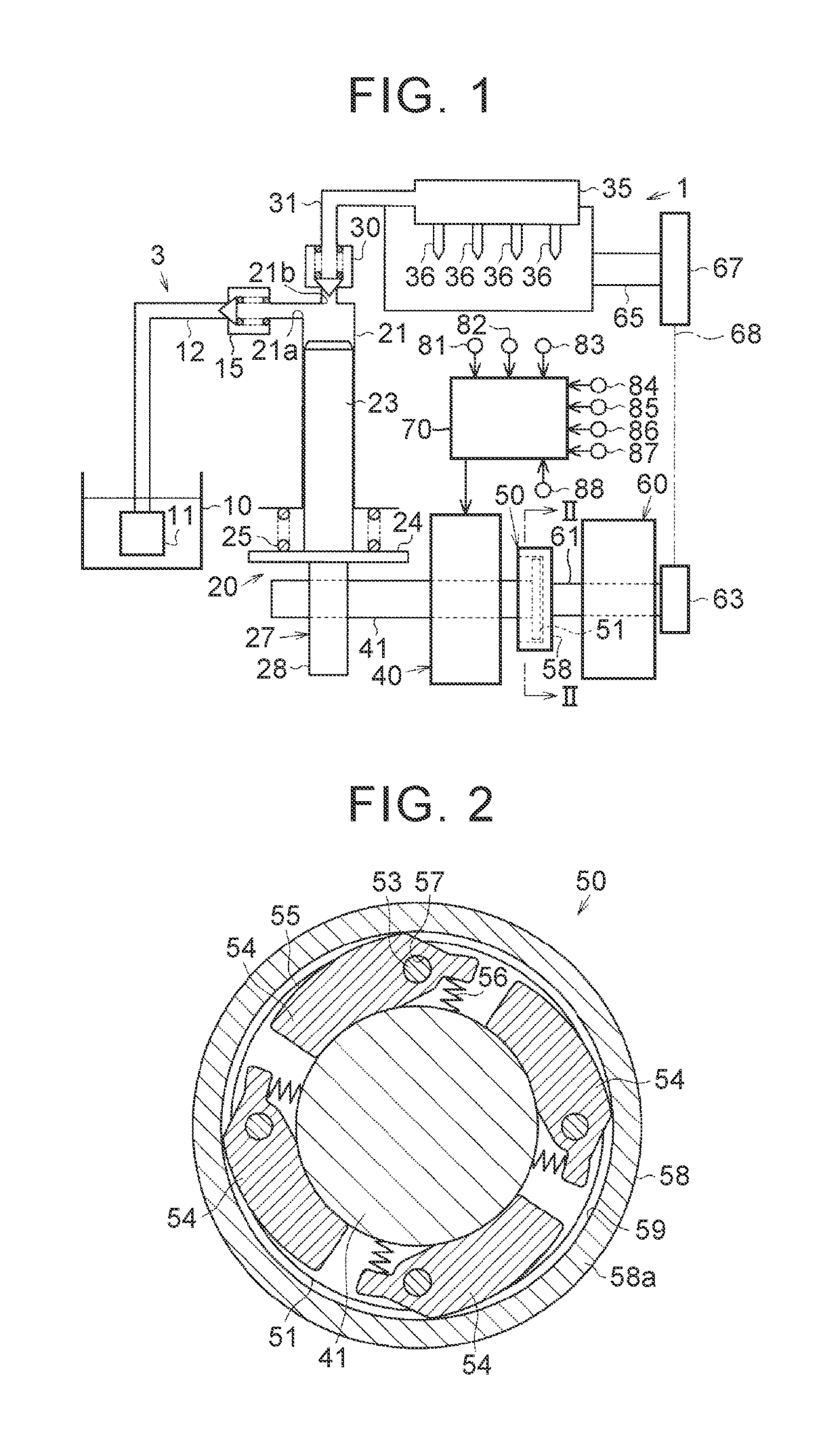
[0030]Hereinafter, a fuel supply apparatus for an internal combustion engine will be described with reference to FIG. 1 to FIG. 6. An internal combustion engine 1 to which the fuel supply apparatus according to the present embodiment is applied is an in-line four-cylinder gasoline engine that is mounted on a vehicle.

[0031]As shown in FIG. 1, in a fuel supply system 3 of the internal combustion engine 1, a feed pump 11, a low-pressure fuel passage 12, a first check valve 15, a high-pressure fuel pump 20, a second check valve 30, a high-pressure fuel passage 31 and a delivery pipe 35 are sequentially connected. The feed pump 11 is an electric pump. The feed pump 11 draws fuel inside a fuel tank 10, and then feeds the fuel to the low-pressure fuel passage 12 under pressure.

[0032]The high-pressure fuel pump 20 includes a cylinder 21 and a plunger 23. The plunger 23 moves up and down inside the cylinder 21. A lifter 24 is fixed to the lower end of the plunger 23. The lifter 24 is urged b...

second embodiment

[0092]In the second embodiment, in the internal combustion engine 1 that is automatically stopped and automatically restarted, when an engine restart is predicted during an automatic stop, the output shaft 41 of the motor 40 is rotated at a rotation speed lower than the engaging rotation speed N1 in advance of the engine restart. The condition for predicting an engine restart during an automatic stop may be a condition other than the condition illustrated as the condition for making affirmative determination in step S41. For example, when a period during which the internal combustion engine 1 is automatically stopped continues for a predetermined period or longer, an automatic restart may be predicted, and the output shaft 41 of the motor 40 may be rotated.

[0093]Not during an automatic stop of the internal combustion engine 1 but during a manual stop where the ignition switch 88 is in an off state, when an engine restart is predicted, the output shaft 41 of the motor 40 may be rotat...


PUM


Abstract

A fuel supply apparatus for an internal combustion engine includes a motor, a fuel pump, an alternator, a centrifugal clutch, and an electronic control unit. The centrifugal clutch is configured to, when the rotation speed of the output shaft of the motor is higher than or equal to an engaging rotation speed, connect the output shaft of the motor with the rotary shaft of the alternator. The engaging rotation speed is a rotation speed higher than a rotation speed of the rotary shaft at which torque that acts on the rotary shaft as a result of generation of electric power by the alternator becomes maximum and is a rotation speed lower than a rotation speed at which torque for driving the high-pressure fuel pump cannot be provided by only the motor at the time when the motor is driven at rated output power.

Description

INCORPORATION BY REFERENCE[0001]The disclosure of Japanese Patent Application No. 2015-180792 filed on Sep. 14, 2015 including the specification, drawings and abstract is incorporated herein by reference in its entirety.BACKGROUND[0002]1. Technical Field[0003]The present disclosure relates to a fuel supply apparatus for an internal combustion engine.[0004]2. Description of Related Art[0005]In a fuel supply apparatus for an internal combustion engine, described in Japanese Patent Application Publication No. 2007-278167 (JP 2007-278167 A), a clutch mechanism is interposed between one end of an output shaft of a motor and an exhaust camshaft of the internal combustion engine, and the other end of the output shaft of the motor and a drive shaft of a fuel pump are connected to each other.[0006]With this fuel supply apparatus, the fuel pump is driven by only the driving force of the motor when the clutch mechanism is placed in a released state, and the fuel pump is driven by the driving f...

Claims


Application Information

Patent Timeline
Patent Type & Authority Applications(United States)
IPC IPC(8): F02D41/30F02M59/02H02K7/00F02B63/04H02P7/00H02K7/108F02M59/10F02D41/06
CPCF02D41/3082F02M59/10F02M59/025H02K7/006F02B63/042H02P7/00H02K7/108F02D41/065F02M39/02F02D41/123F02D41/3845F02D2250/04F02N11/0814F16D43/18F16D2043/145
Inventor ASAYAMA, KAZUHIRO
Owner TOYOTA JIDOSHA KK
Why Eureka
Try Eureka