Wind turbine with a brake dust collector

Active Publication Date: 2017-03-16
SIEMENS GAMESA RENEWABLE ENERGY AS
View PDF3 Cites 11 Cited by
  • Summary
  • Abstract
  • Description
  • Claims
  • Application Information

AI Technical Summary

Benefits of technology

[0022]The brake dust released during the braking operation will be prevented from

Problems solved by technology

During braking operation, the caliper presses the brake pads onto the surface of th

Method used


Image

  • Wind turbine with a brake dust collector
  • Wind turbine with a brake dust collector
  • Wind turbine with a brake dust collector

Examples


Example

[0026]Some of the embodiments will be described in detail, with reference to the following figures, wherein like designations denote like members, wherein:

[0027]FIG. 1 shows a simplified diagram of a direct-drive wind turbine;

[0028]FIG. 2 shows a simplified wind turbine of FIG. 1 with a different cooling airflow.

DETAILED DESCRIPTION

[0029]The illustration in the drawing is schematic. It is noted that in different figures, identical elements or features are provided with the same reference signs. In order to avoid unnecessary repetitions elements or features which have already been elucidated with respect to a previously described embodiment are not elucidated again at a later position of the description.

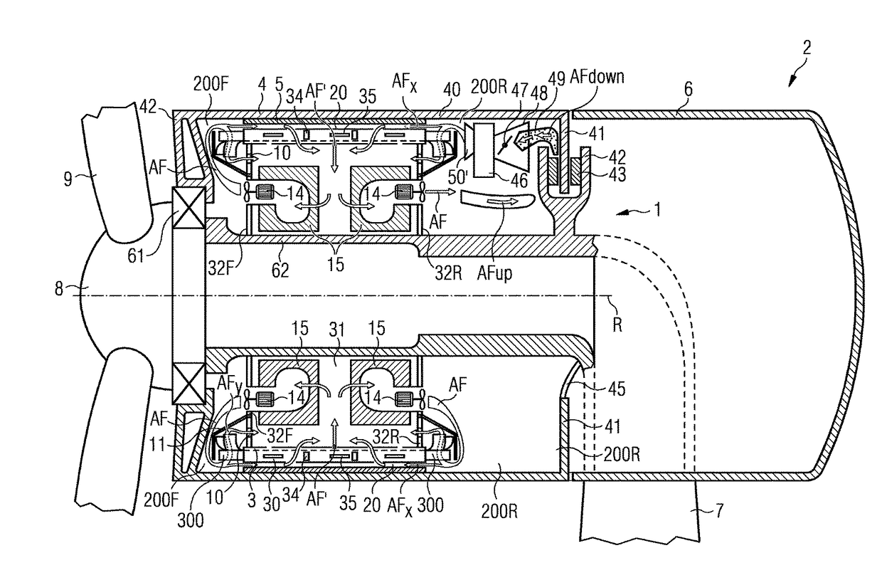
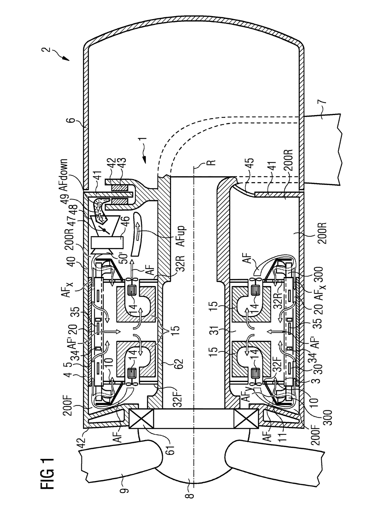
[0030]FIG. 1 is a simplified diagram of a direct-drive wind turbine 2. A nacelle 6 is mounted on top of a tower 7. A hub 8 with rotor blades 9 is mounted to a permanent-magnet generator 3, 4 comprising an outer rotor 4 and an inner stator 3 which are connected rotatable to each other ...


PUM


Abstract

A wind turbine including a generator with a stator and a rotor, a cooling arrangement, a wind turbine brake including a brake disk and a caliper with brake pads is provided. An air duct with a filter is located near the brake pads of the caliper. During the operation of the cooling arrangement, a part of the air flow is guided via the brake pads. The brake dust produced by the brake pads during operation of the brake will be reduced by the filter of the air duct.

Description

CROSS-REFERENCE TO RELATED APPLICATION[0001]This application claims priority to European Application No. 15185338.9 having a filing date of Sep. 15, 2015 the entire contents of which are hereby incorporated by reference.FIELD OF TECHNOLOGY[0002]The following relates to a wind turbine and a method to collect brake dust of a wind turbine brake.BACKGROUND[0003]EP 2 182 619 A shows a wind turbine comprising a stator and a rotor and a cooling arrangement. The cooling arrangement comprises an air cooling and a liquid cooling device which are connected by an air-to-liquid heat exchanger, which is applied to transport heat out of the generator by the cooling liquid.[0004]EP 2 902 619 shows a cooling arrangement for a wind turbine with an outer rotor and an inner stator. A cooling arrangement is realized to guide an air flow over the outside rotor to transfer heat from the generator to the cooling air flow.[0005]EP 2 333 321 A shows a wind turbine with a brake system comprising brake disk in...

Claims


Application Information

Patent Timeline
IPC IPC(8): F03D80/60F03D80/80F03D9/00F03D9/25F03D1/06F03D7/02
CPCF03D80/60F03D1/06F03D7/0248F03D80/88F03D9/25F03D80/82F03D9/002F03D7/0244F03D80/00F05B2220/7066F05B2260/20F05B2260/63F05B2260/64F05B2260/902Y02E10/72F03D80/55
Inventor AIROLDI, GIOVANNIHANSEN, KIM GRANLYSOERENSEN, PETER HESSELLUND
Owner SIEMENS GAMESA RENEWABLE ENERGY AS
Why Eureka
Try Eureka