Device for the Separation of Particles Using a Bulk Acoustic Wave Field

a particle separation and bulk acoustic wave technology, applied in the field of particle separation, can solve the problems of affecting the cell physiology and viability, requiring contact between the particle, and limiting the volumetric flow rate of the technique,

Active Publication Date: 2017-03-23
CARNEGIE MELLON UNIV
View PDF4 Cites 21 Cited by
  • Summary
  • Abstract
  • Description
  • Claims
  • Application Information

AI Technical Summary

Benefits of technology

[0007]According to one embodiment of the present invention is a device employing standing bulk acoustic waves to separate particles flowing in a channel, where the nodes of the standing waves are at an angle to the direction of flow of a fluid through the channel. Within the microfluidic channel, the particles experience an acoustic force towards the acoustic nodes, which is proportional to the particle volume. The acoustic force is opposed by the drag force on the particle from the fluid, which is proportional to particle radius. Consequently, particles with a larger volume move faster towards acoustic nodes than smaller volume particles. By applying the acoustic forces at an angle to the direction of flow, it is possible to separate particles by size or other characteristic in a continuous flow device.

Problems solved by technology

Several methods exist for particle separation, but each has its own drawbacks.
When the particles are biological cells, modifying the cells to obtain these properties can adversely impact the cell physiology and viability, rendering the techniques unusable for cellular engineering applications.
Hydrodynamic separation mechanisms, including flow cytometry, can be continuous and passive, but these techniques are limited in volumetric flow rate or require contact between the particle and channel structure.
These types of devices, which are typically molded with soft polymers (such as in a polydimethylsiloxane), are not robust enough for use outside of a lab and are expensive to fabricate.
Further, the flowrate of fluid in the device is limited because the useful standing waves are confined to a distance from the bottom surface of the channel, typically resulting in a shallow channel.

Method used


Image

  • Device for the Separation of Particles Using a Bulk Acoustic Wave Field
  • Device for the Separation of Particles Using a Bulk Acoustic Wave Field
  • Device for the Separation of Particles Using a Bulk Acoustic Wave Field

Examples


Embodiment Construction

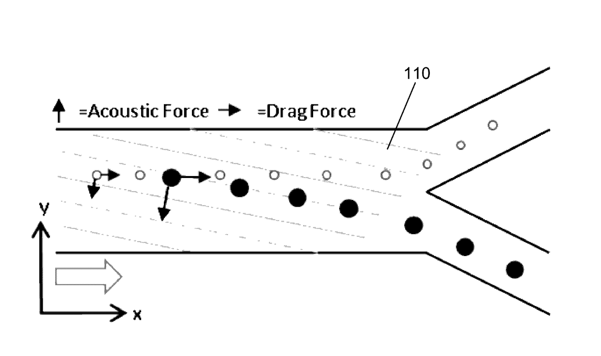
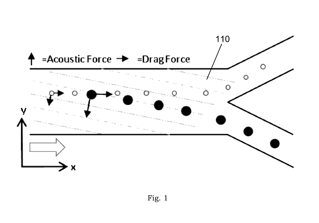
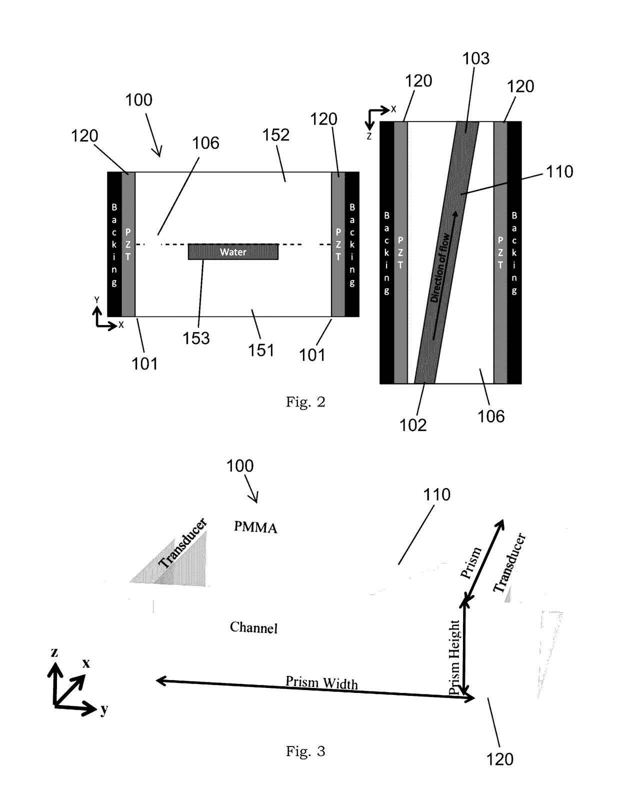
[0017]According to one embodiment, the separation device comprises a prism 100, a microfluidic channel 110 within the prism 100, and a pair of bulk acoustic wave generators 120 attached to the prism. As shown in FIG. 2, the prism 100 is generally rectangular in shape and is constructed from poly (methyl methacrylate) (PMMA) in one embodiment, although other rigid polymers or materials can be used. The acoustic wave generators 120 are coupled to opposing external sides 101 of the prism 100 and are used to create standing or traveling waves within the microchannel 110. However, separation along node lines is more effective in standing wave environments. To create standing waves, the acoustic wave generators 120 are positioned parallel to each other on opposing sides of the channel 110. In one embodiment, the acoustic wave generators 120 are lead zirconate titanate (PZT) transducers; however, other types of bulk acoustic wave generators can be used. FIGS. 2-3 depict alternative embodim...


PUM

PropertyMeasurementUnit
sizeaaaaaaaaaa
angleaaaaaaaaaa
angleaaaaaaaaaa

Abstract

The disclosure describes a prism containing a microfluidic channel. By coupling bulk acoustic wave generators to opposing sides of the prism, a standing bulk acoustic wave field can be excited in the prism and in the microfluidic channel. Because the microfluidic channel is titled with respect to the nodes of the bulk acoustic wave field, the prism microfluidic channel device can be used to separate microparticles and biological cells by size, compressibility, density, shape, or mass distribution. This technology enables high throughput cell sorting for biotechnology applications such as cancer cell detection.

Description

CROSS-REFERENCE TO RELATED APPLICATIONS[0001]This application claims the benefit under 35 U.S.C. §119 of Provisional Application Ser. No. 62 / 283,999, filed Sep. 17, 2015, and Provisional Application Ser. No. 62 / 390,207, filed Mar. 22, 2016, each of which is incorporated herein by reference.STATEMENT REGARDING FEDERALLY SPONSORED RESEARCH[0002]This invention was made with government support under Grant No. CMMI-1235145 awarded by the U.S. National Science Foundation. The government has certain rights in the invention.BACKGROUND OF THE INVENTION[0003]This invention relates generally to the separation of particles. More specifically, the invention relates to the separation of particles suspended in a fluid through the use of acoustic forces.[0004]Separating and sorting particles is an important activity in many applications including biological research, cellular engineering, biological and chemical analyses, and lab-on-a-chip technologies. Several methods exist for particle separation...

Claims


Application Information

Patent Timeline
Patent Type & Authority Applications(United States)
IPC IPC(8): B01L3/00G01N15/10
CPCB01L3/502761G01N2015/0065B01L3/502715B01L3/502776B01L3/502707B01L3/50273G01N2015/0019B01L2300/12B01L2200/025B01L2300/0867B01L2200/12B01L2400/0436B01L2200/0652G01N2015/1081G01N15/1056G01N1/4077G01N15/0255
Inventor DAUSON, ERIN R.GREVE, DAVID W.OPPENHEIM, IRVING J.GREGORY, KELVIN B.HEALY, GREGORY P.
Owner CARNEGIE MELLON UNIV
Why Eureka
Try Eureka