Method for producing a heat exchanger and relevant heat exchanger

a technology of heat exchanger and heat exchanger, which is applied in the field of heat exchangers, can solve the problems of not being able to obtain inter-distances, circuit damage, and over-maximum allowable operating temperatures, so as to reduce overall dimensions, cost and weight, and reduce engine dimensions

Inactive Publication Date: 2017-03-23
IST NAZ DI FISICA NUCLEARE
View PDF9 Cites 5 Cited by
  • Summary
  • Abstract
  • Description
  • Claims
  • Application Information

AI Technical Summary

Benefits of technology

[0036]In this manner, namely due to the efficiency of the heat exchange accomplished, it is possible to considerably reduce

Problems solved by technology

For example, in the electronic field, in order to allow the current electronic components to perform their tasks more and more quickly, high-powered integrated circuits have been produced; however such circuits generate such heat fluxes that, if they are not efficiently removed, cause the maximum allowable operating temperatures to be exceeded and the circuits to be consequently damaged.
Due to technical reasons, by p

Method used


Image

  • Method for producing a heat exchanger and relevant heat exchanger
  • Method for producing a heat exchanger and relevant heat exchanger
  • Method for producing a heat exchanger and relevant heat exchanger

Examples


Embodiment Construction

[0046]While the invention is susceptible of various modifications and alternative forms, some disclosed relevant embodiments are shown in the drawings and will be described below in detail.

[0047]It should be understood, however, that there is no intention to limit the invention to the specific embodiments disclosed, but, on the contrary, the intention of the invention is to cover all modifications, alternative constructions and equivalents falling within the scope of the invention as defined in the claims.

[0048]Therefore in the description below the use of “for example”, “etc”, “or”, “otherwise” indicates non-exclusive alternatives without limitation unless otherwise defined; the use of “also” means “including, but not limited to” unless otherwise defined; the use of “including / comprising” means “including / comprising but not limited to,” unless otherwise defined.

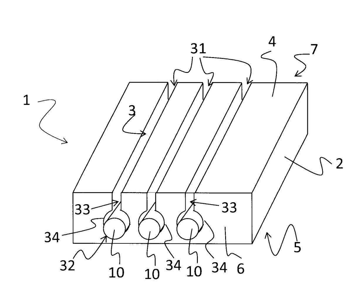
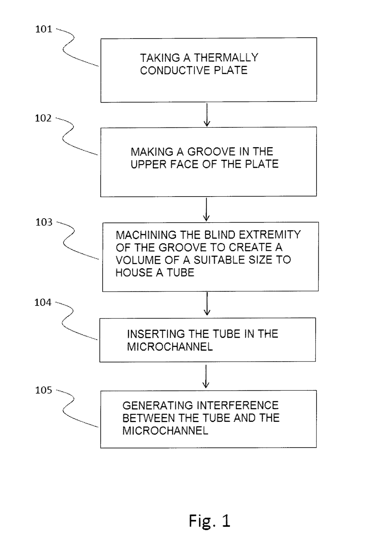
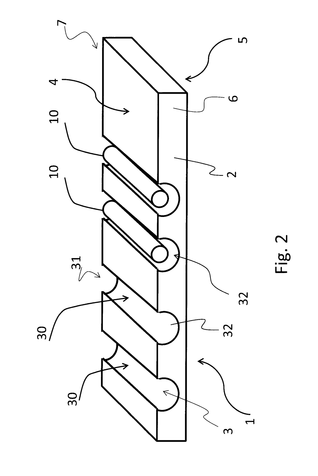
[0049]The flow chart of FIG. 1 allows a method for producing a heat exchanger 1 to be appreciated in its general aspect, f...


PUM

PropertyMeasurementUnit
Diameteraaaaaaaaaa
Lengthaaaaaaaaaa
Pressureaaaaaaaaaa

Abstract

The invention relates to a method for producing a heat exchanger, wherein at least one microchannel, placed within a plate having an upper face and a lower face and precisely arranged between said upper face and lower face is obtained by making a groove on the upper face of the plate, said groove extending between an open extremity facing on the upper face and a blind extremity placed inside the plate, and machining the blind extremity of the groove to create a volume of a suitable size to house a tube inserted in the microchannel, said tube being fixed inside the microchannel by generating an interference between the tube and the microchannel. The invention relates also to a heat exchanger obtained by such method.

Description

TECHNICAL FIELD[0001]The present invention relates to the field of heat exchangers and to methods for producing them.[0002]More precisely the present invention relates to microchannel heat dissipating systems.[0003]Particularly, the invention relates to a method according to the preamble of claim 1 and to a heat exchanger obtained by such method.[0004]The invention is preferably and advantageously applied for cooling systems producing radionuclides, particularly radiopharmaceuticals, for cooling heat engines, for cooling electronic components and circuits, for producing power targets for medical, energy and basic research applications, and for material treatment.PRIOR ART[0005]Nowadays in many technological fields it is necessary to dissipate high specific powers (meanings power per unit surface or volume).[0006]For example, in the electronic field, in order to allow the current electronic components to perform their tasks more and more quickly, high-powered integrated circuits have...

Claims


Application Information

Patent Timeline
IPC IPC(8): F28F3/12H01L21/48H01L23/427F28F21/00B23P15/26
CPCF28F3/12F28F21/00B23P15/26H01L23/427H01L21/4882F28F2260/02F01P2070/52F28F2275/122F28F2275/125F28F2275/127F01P3/02F01P2003/021F01P2003/024F28F2275/12F28D2021/0029G21G1/10H01L2924/0002H01L2924/00
Inventor MASTINU, PIERFRANCESCOMARIGO, SELVINO
Owner IST NAZ DI FISICA NUCLEARE
Why Eureka
Try Eureka