Method for producing a climate control box

a technology for climate control boxes and boxes, which is applied in vehicle heating/cooling devices, transportation and packaging, and other domestic articles, etc. it can solve the problems of high capital investment in physical foaming processes, deformation and failure over the life cycle of components, and increase overall material costs, so as to minimize raw material costs and minimize inherent stress

Inactive Publication Date: 2017-03-30
HANON SYST
View PDF2 Cites 0 Cited by
  • Summary
  • Abstract
  • Description
  • Claims
  • Application Information

AI Technical Summary

Benefits of technology

[0012]In concordance with the instant disclosure, an improved process for forming polymeric components of a HVAC system, wherein the process utilizes conventional injection molding equipment, minimizes raw material costs, and minimizes inherent stress is surprisingly discovered.

Problems solved by technology

However, physical foaming processes involve high capital investment, as specialty molding equipment is required to inject the gas into the polymeric material, and to maintain the molten polymeric material in a highly compressed state prior to introduction into the molding chamber.
Once the polymeric material is cooled in the mold, inherent stresses may form within the molded component, leading to deformation and failure over the life cycle of the component.
However, the addition of hollow glass spheres to the polymeric material increases overall material costs.
Additionally, hollow glass sphere-containing resins are not offered by many suppliers, making sourcing of suitable materials more difficult and costly.
However, talc has a higher density than polypropylene, thereby increasing the overall weight of the material.
However, the reduction of the concentration of talc may be undesirable for multiple reasons.
Initially, the physical properties of the base resin may be negatively affected by removing or substituting the talc.
Additionally, base resin blends having less than 20% talc are not commonly manufactured by suppliers, and costs to obtain these alternative base resins may be prohibitively high.
In addition to the aforementioned shortcomings in the art, part fit-and-finish and dimensional control is difficult to achieve due to increasingly complex part geometries combined with the desire for reduced wall thicknesses.
For example, thinner wall sections make it progressively harder to inject molten material into a mold and achieve even pack pressure.

Method used


Image

  • Method for producing a climate control box
  • Method for producing a climate control box

Examples


Embodiment Construction

[0018]The following detailed description and appended drawings describe and illustrate various embodiments of the invention. The description and drawings serve to enable one skilled in the art to make and use the invention, and are not intended to limit the scope of the invention in any manner. In respect of the methods disclosed, the steps presented are exemplary in nature, and thus, the order of the steps is not necessary or critical.

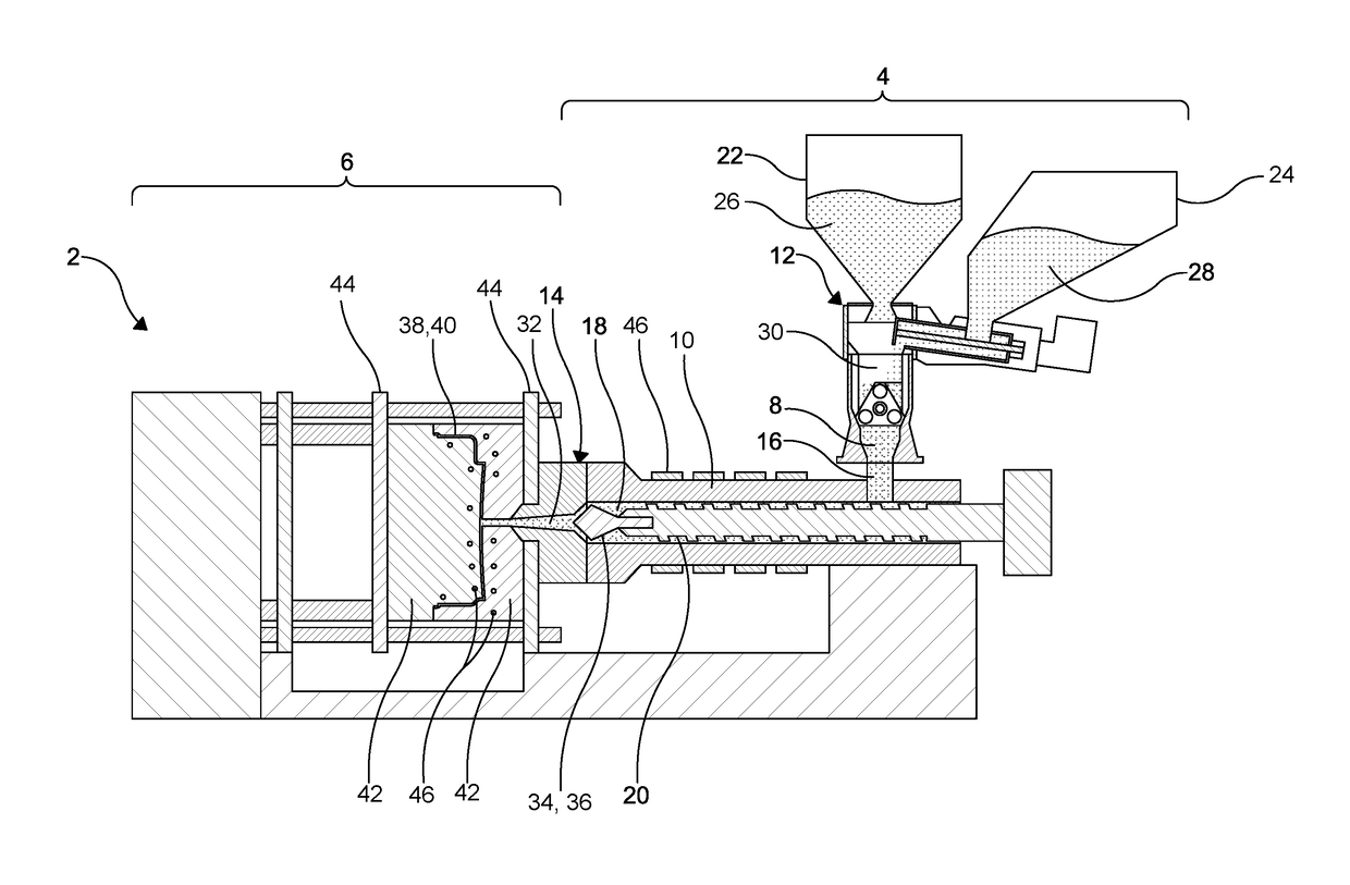
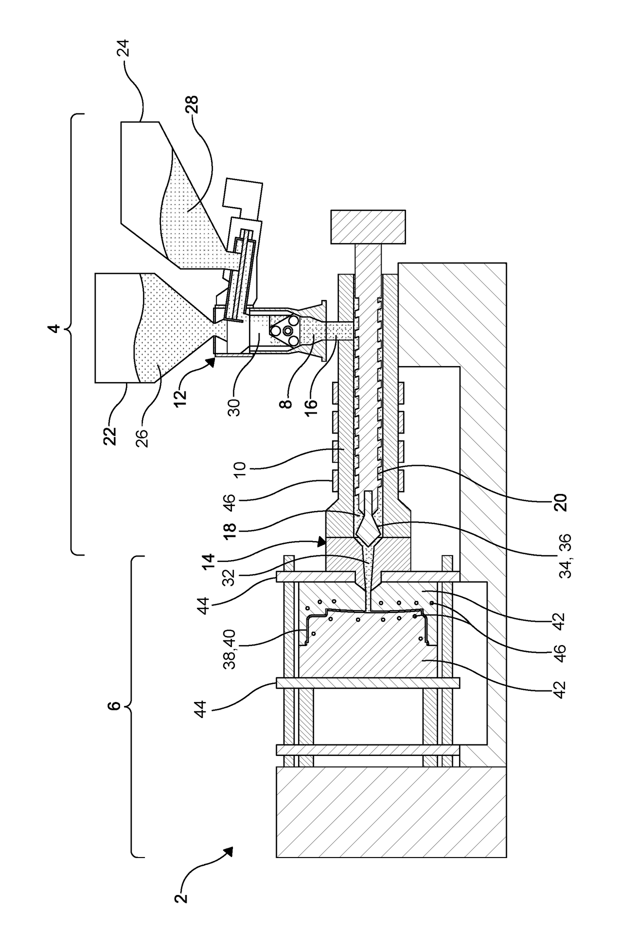
[0019]As shown in the FIGURE, a molding system 2 for carrying out an embodiment of the disclosure is shown. The molding system 2 includes an injector 4 and a mold 6 in fluid communication with each other, wherein the injector 4 is configured to provide a flow of a composition 8 to the mold 6.

[0020]The injector 4 includes a barrel 10, a feed system 12, and a head 14. The barrel 10 of the injector 4 includes at least one inlet 16 in fluid communication with the feed system 12, and an outlet 18 in communication with the head 14. The barrel 10 further inc...


PUM

PropertyMeasurementUnit
temperatureaaaaaaaaaa
pressureaaaaaaaaaa

Abstract

A method of forming a component of a vehicle heating, ventilation, and air-conditioning system from polymeric material includes providing a molding system including at least one mold cavity defining the component. A base resin is introduced to the mold system via an inlet. A chemical foaming agent is blended with the base resin to form a composition. The composition is then further heated and blended under pressure, wherein the chemical foaming agent decomposes within the composition. The composition is introduced to the mold cavity, wherein a reduced minimized pressure of the mold cavity facilitates initiation of a nucleation of the composition, wherein the composition expands to fill the mold cavity.

Description

CROSS-REFERENCES TO RELATED APPLICATIONS[0001]This patent application claims priority to U.S. Provisional Patent Application No. 62 / 233,733, filed on Sep. 28, 2015, the disclosure of which is incorporated herein by reference in its entirety.FIELD OF THE INVENTION[0002]The invention relates to a method for producing a heating, ventilation, and air conditioning (HVAC) box for a vehicle, and more particularly, to producing a HVAC box for a vehicle using chemical foaming.BACKGROUND[0003]There is a continuing effort in the automotive industry to reduce vehicle weight in order to improve vehicle efficiency. Particularly, a trend exists to minimize weight of polymeric components of heating, ventilation, and air-conditioning (HVAC) systems through changes that reduce part thickness and densities.[0004]One current solution for minimizing the weight of polymeric HVAC components is known as physical foaming. Physical foaming involves entraining a compressed gas, such as Nitrogen, into a molten...

Claims


Application Information

Patent Timeline
Patent Type & Authority Applications(United States)
IPC IPC(8): B29C44/42B60H1/00B29C44/58B29C44/60B29C44/02B29C44/34
CPCB29C44/42B29C44/02B29C44/3449B29C44/58B29L2031/30B60H1/00514B29K2101/12B29K2105/0005B29K2105/043B29C44/60B29K2023/06B29K2023/12B29K2027/06B29K2033/04B29K2055/02B29K2075/00B29K2077/00B29K2105/16B29K2105/251B29K2223/083B29K2995/0015B29K2995/0091B29L2031/3002B29C44/3442B29C44/428B29C45/14795B29C45/1816B29C2045/308
Inventor SPROULE, MICHAELCARDWELL, BRIAN
Owner HANON SYST
Why Eureka
Try Eureka