Oil Lubricated Compressor

a compressor and oil lubrication technology, applied in the field of compressors, can solve the problems of tripping the breakers, difficult starting and re-starting of the induction motor, etc., and achieve the effects of low start voltage, low re-start voltage, and high torque to voltage characteristics

Active Publication Date: 2017-04-13
BLACK & DECKER INC
View PDF14 Cites 5 Cited by
  • Summary
  • Abstract
  • Description
  • Claims
  • Application Information

AI Technical Summary

Benefits of technology

[0005]In an embodiment, an oil lubricated compressor, can have a universal motor to drive a pump and a fan. The compressor can have a low start voltage, a low re-start voltage, high torque to voltage characteristics, and a long operating life. The operating life of the compressor and / or the universal motor can be in a range of 300 hrs to 600 hrs, or greater. The universal motor can be a brushed universal motor, optionally having an electrographite grade brush. The universal motor can also be a brushless universal motor.
[0007]In an embodiment, an improved universal motor is used to power a pump. The universal motor can be a brushed motor that can run on alternating and / or direct current applied voltages. The universal motor has a torque generated from a field in the armature of the motor that is created through direct contact with the armature and / or the commutator through a brush system. The direct contact of the brush system to the armature and / or the commutator has fewer losses of induced field and helps to generate equivalent, or higher, starting torque values at a lower amperage than an induction motor. An interface and / or air gap can exist between the stator and the rotor of the universal motor, whether the motor is a brushed motor or a brushless motor. The universal motor has an improved commutator design that includes brushes having an electrographite grade, at least a doubled axial length as compared to typical universal motors and increased tangential dimension as compared to typical universal motors, resulting in a longer brush life over typical universal motors that use brushes having lower resin bonded grades and higher voltage drop characteristics at start and / or re-start. The universal motor disclosed herein can provide a higher torque at a lower amperage value than typical universal motors that use brushes having lower resin bonded grades and having higher voltage drop characteristics. The universal motor disclosed herein can overcome the viscosity of the oil lubricating the pump and can readily start in cold weather, as well as under low voltage, or under adverse conditions.
[0008]In addition, the armature in the universal motor is larger in length and diameter than typical universal motors, which helps to generate additional torque. The universal motor of the present invention has a high torque value that uses a low starting current to prevent breakers from tripping during starting or re-starting of the pump in cold weather, as well as low voltage, or adverse conditions.

Problems solved by technology

However, typical induction motor-driven oil lubricated compressor pumps have a low torque value and thereby struggle or fail to overcome the viscosity of the lubricating oil, thereby resulting in difficulty starting and re-starting the induction motor.
Because of the high current required by the induction motor, use of extension cords with such induction motors are known to trip the breakers on the compressor, or in the electrical panel providing power to the compressor.

Method used


Image

  • Oil Lubricated Compressor
  • Oil Lubricated Compressor
  • Oil Lubricated Compressor

Examples


first embodiment

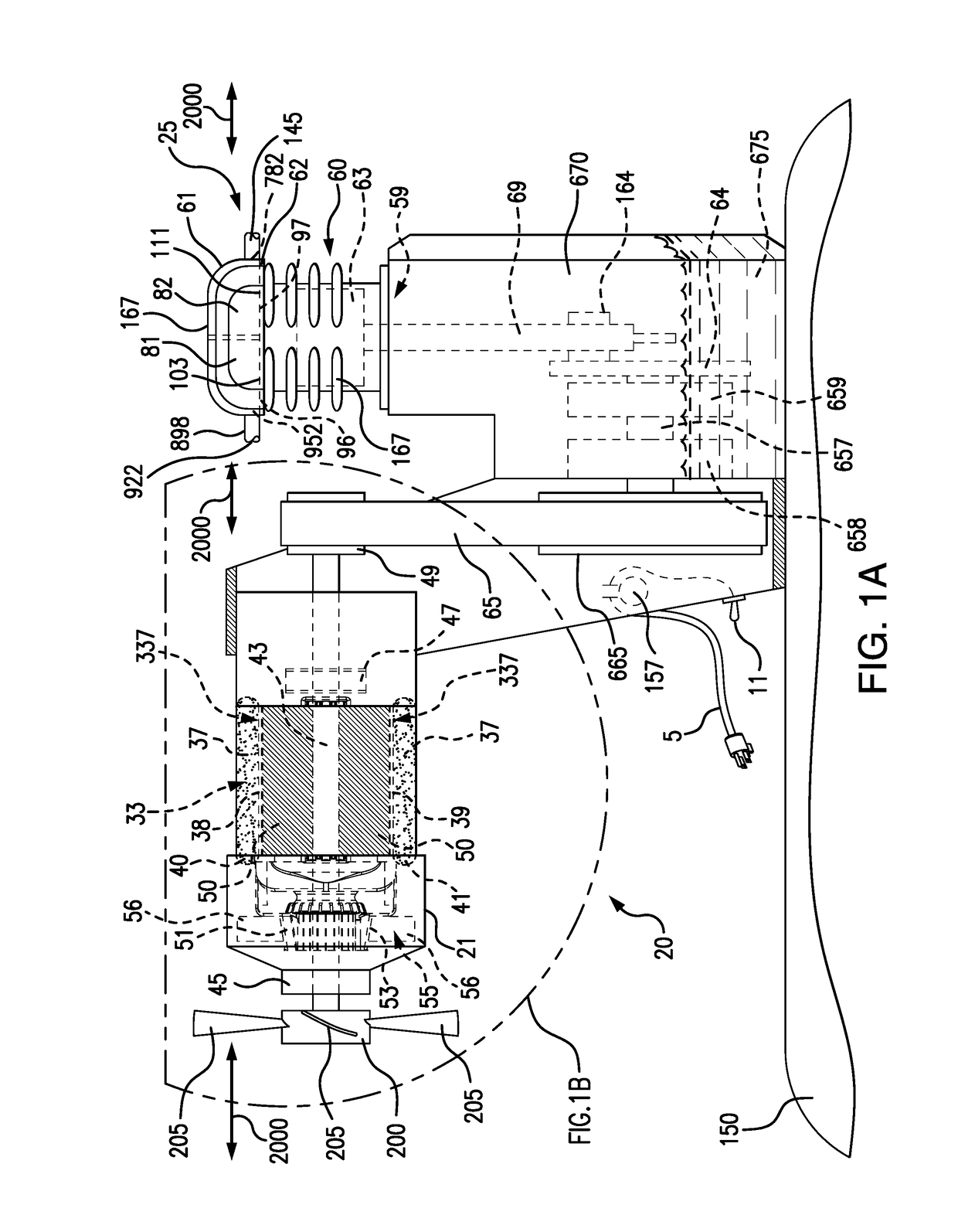
[0022]FIG. 1A shows an oil lubricated compressor assembly 20 (herein as “compressor assembly”20) for producing compressed air. The compressor assembly 20 can have a universal motor 33, a fan 200 and a pump assembly 25 which compresses an air feed. The universal motor 33 can drive a fan 200 and a pump member 59 of the pump assembly 25. The pump assembly 25 feeds the compressed air to an air or gas containing structure, such as a compressed air tank 150. The compressed air can be retained in the compressed air tank 150 and can be released according to user demand through a pneumatic air hose, or other means, and can power a variety of tools. The compressor assembly 20 can have a low start voltage, a low re-start voltage, high torque to voltage characteristics and a long operating life, such as 300 hrs to 600 hrs, or greater.

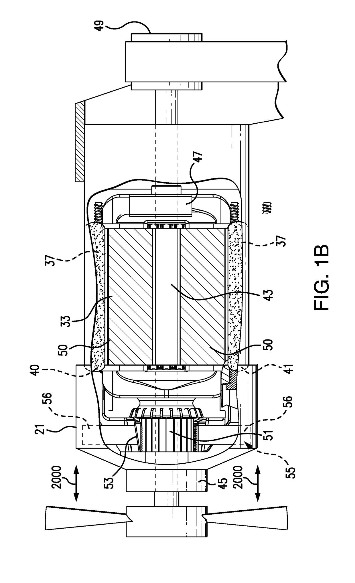
[0023]The Universal Motor

[0024]The universal motor 33 can have a stator 37 with an upper pole 38 around which upper stator coil 40 is wound and / or configured. FIG....

second embodiment

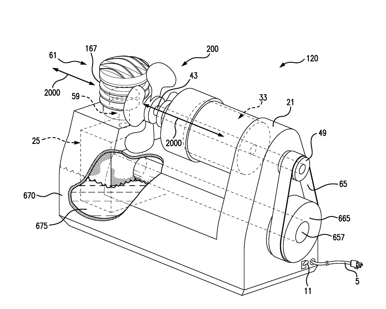
[0056]FIG. 2 illustrates a universal motor-driven oil lubricated compressor assembly, compressor assembly 120. In the embodiment of compressor assembly 120, the fan 200 is positioned between the universal motor 33 and the cylinder head 61 of the pump assembly 25 to cool both the universal motor 33 and the cylinder head 61. The direction of the cooling air stream 2000 can be determined by the direction of rotation of the fan 200. The direction of the cooling air stream 2000 can be either in a direction from the universal motor 33 to the cylinder head 61, or in an opposite direction from the cylinder head 61 to the universal motor 33. The cylinder head 61 can have fins 167 formed thereon to facilitate heat dissipation from the pump 59.

[0057]In an embodiment, the cooling air stream 2000 can have a volumetric flow rate of 50 SCFM to 100 SCFM; and / or heat transfer rates of 60 BTU / min to 200 BTU / min

[0058]The compressor assembly 20 using the universal motor 33 described herein can achieve ...


PUM


Abstract

An oil lubricated compressor having a universal motor, efficient starting and re-starting characteristics, and a long operating life. The oil lubricated compressor can have a brushed or brushless universal motor which can drive a cooling fan and a pump. The universal motor can achieve a high torque to voltage ratio, as well as a high torque to current ratio, upon starting or re-starting of the compressor. Optionally, the oil lubricated compressor can use a single cooling fan disposed in the compressor at a location which is between the universal motor and a cylinder head of the pump.

Description

CROSS-REFERENCE TO RELATED APPLICATIONS[0001]This patent application claims benefit of the filing date of copending U.S. provisional patent application No. 62 / 238,306 entitled “Universal Motor-Driven Oil Lube Compressor” filed on Oct. 7, 2015.FIELD OF THE INVENTION[0002]The present invention relates to the field of compressors and, in particular, to an oil lubricated compressor for compressing air.INCORPORATION BY REFERENCE[0003]This patent application incorporates by reference in its entirety U.S. provisional patent application No. 62 / 238,306 entitled “Universal Motor-Driven Oil Lube Compressor” filed on Oct. 7, 2015. This patent application also incorporates by reference in its entirety U.S. Pat. No. 7,081,698 entitled “Efficient Motor” issue on Jul. 25, 2006.BACKGROUND OF THE INVENTION[0004]A compressor can be used to provide compressed air to a pneumatically powered tool. A compressor can have a prime mover for driving the compressor, and a tank for storing the compressed air. T...

Claims


Application Information

Patent Timeline
Patent Type & Authority Applications(United States)
IPC IPC(8): F04B39/02F04B35/04F04D25/08F04B39/06F04B49/02H01R39/20H02K7/10H02K13/10H02K23/64H02K29/00H01R39/60F04D25/06H02K9/06
CPCF04B39/0276H02K2213/03F04B35/04F04D25/082F04B39/066F04B49/02H02K9/06H02K7/1004H02K13/10H02K23/64H02K29/00H01R39/60H01R39/20F04B2203/0202F04B2203/0201F04D25/06F04B27/053F04B35/06F04B41/02F04B39/06
Inventor VOS, STEPHEN J.HATHCOCK, LANCE S.VINTZEL, JAMESMCFARLAND, DALTON E.
Owner BLACK & DECKER INC
Why Eureka
Try Eureka