Delayed Ignition Control Device

a control device and delay time technology, applied in the direction of electric ignition installation, mechanical equipment, machines/engines, etc., can solve the problems of affecting the actual use of the shut-off mode, endangering the physical affecting the safety of the operator, so as to achieve convenient adjustment of the delay time and simple structure , the effect of reliable operation

Inactive Publication Date: 2017-04-20
YUYAO AOXIN ELECTRICAL APPLIANCE
View PDF0 Cites 0 Cited by
  • Summary
  • Abstract
  • Description
  • Claims
  • Application Information

AI Technical Summary

Benefits of technology

[0016]The present invention has the advantages of simple str...

Problems solved by technology

Having the tool resart in such a sudden fashion could result in damage to the chainsaws themselves and also endanger the physical safety of the operator.
Such a shut-off mode poses potentially huge safety implications in actual use.
When the rotation speed of the general small gasoline engine exceeds the maxim...

Method used


Image

  • Delayed Ignition Control Device
  • Delayed Ignition Control Device
  • Delayed Ignition Control Device

Examples


first embodiment

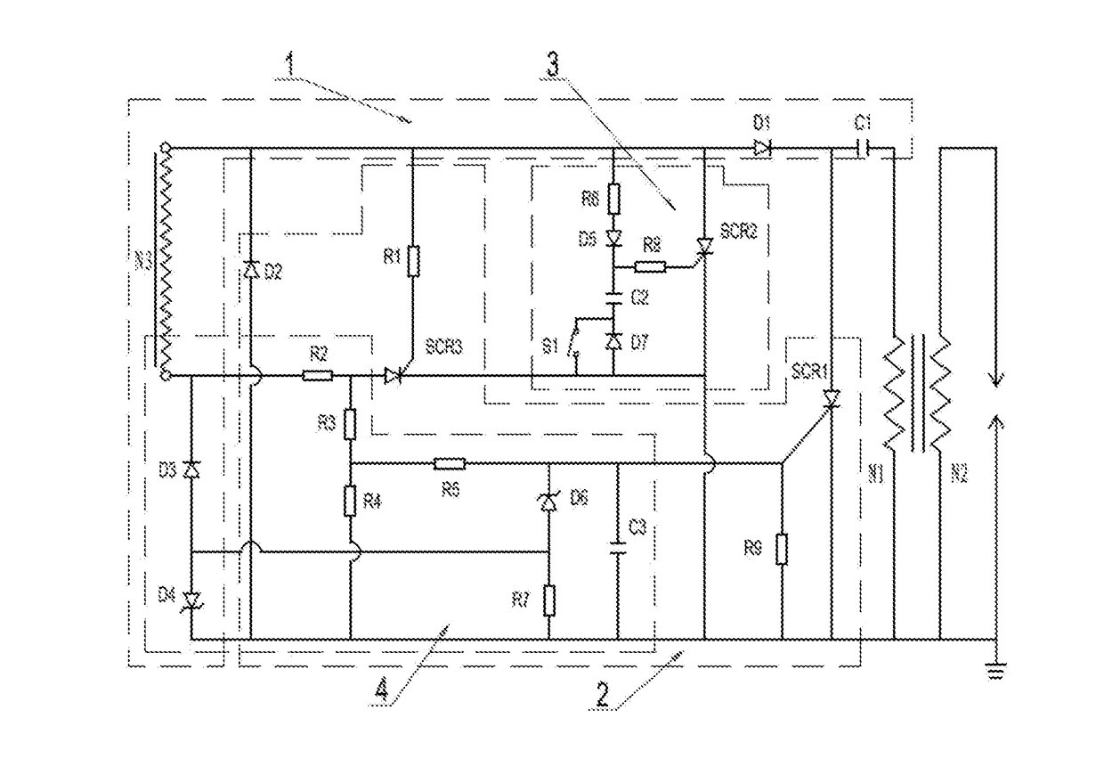
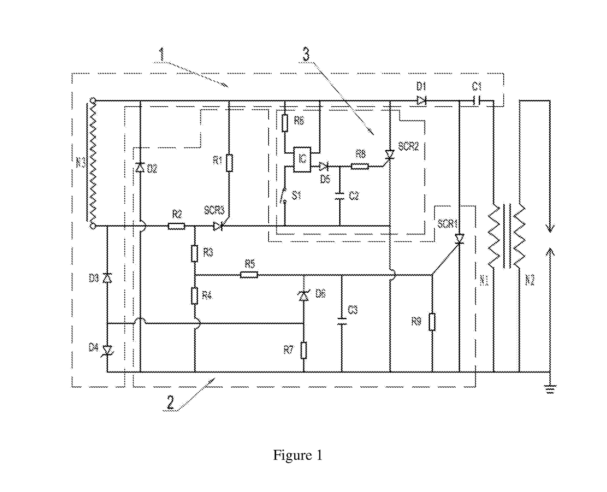
[0022]FIG. 1 displays the circuit diagram of the present invention. The delayed ignition control device of the present invention includes a charging circuit 1, an ignition time control circuit 2 and a delayed ignition control circuit 3.

[0023]The charging circuit 1 includes a power coil N3, an energy-saving capacitor C1, a diode D1, a diode D1, a diode D3 and a voltage-regulator tube D4. The power coil N3 is connected to an external power supply; the anode of the diode D1 is connected to the initial end of the power coil N3, and the cathode is connected to the energy-saving capacitor Cl. The other end of the energy-saving capacitor C1 is connected to one end of the ignition coil N1, and the other end of the power coil N3 is connected to the other end of the ignition coil N1 and is grounded. The cathode of the diode D3 is connected to the tail end of the power coil N3; the anode of the diode D3 is connected to the positive electrode of the voltage-regulator tube D4, and the negative e...

second embodiment

[0043]The working principle of the second embodiment is as follows:

[0044]Specifically speaking, when the gasoline engine rotates, the power coil N3 cuts the magnetic lines, and the magnetic induction pulse on the power coil N3 passes through a circuit consisting of the power coil N3, the diode D1, the energy-saving capacitor C1 and the primary winding N1 of the ignition coil to charge the energy-saving capacitor C1. The negative half-wave of the magnetic induction pulse on the power coil N3 passes through the circuit consisting of the power coil N3, the resistors R2, R3 and R5, the silicon controlled SCR1 and the diode D2 to trigger the silicon controlled SCR1 such that the energy-saving capacitor C1 can perform instant discharge through the silicon controlled SCR1 and the primary coil N1; the secondary coil N2 generates a high voltage to break down the spark plug to discharge and ignite the compressed fuel gas in the engine cylinder, and then the engine works.

[0045]When the shut-of...


PUM


Abstract

A delayed ignition control device comprises a charging circuit and a delayed ignition control circuit. In the delayed ignition control circuit, the resistor R6 is connected between the positive electrode of the input end of the photo coupling IC and the initial end of the power coil N3; the shut-off switch S1 is connected between the negative electrode of the input terminal of the photo coupling IC and the ground; the collector electrode of the photo coupling IC is connected with the initial end of the power coil N3; the output end of the photo coupling IC is connected with the anode of the diode D5; the voltage holding capacitor C2 is connected between the negative electrode of the diode D5 and the ground; and the resistor R8 is connected with the negative electrode of the diode D5 and the controller electrode of the silicon controlled SCR2.

Description

BACKGROUND OF THE INVENTION[0001]Technical Field[0002]The present invention relates to ignition devices, in particular to an ignition control device with a delayed ignition function.[0003]Description of Related Art[0004]Existing forestry tools such as chainsaws usually use general small gasoline engines as power sources. To stop the engine usually requires the user pressing a button to cut off the current in the power coil of the magnetic motor type ignition control device, which directly short circuits the power coils such that the power coil stops working. However, once the button is released, the ignition recovers, and the engine continues to rotate. Chainsaws are usually manually held while in operation. During lumbering, if an operator presses the shut-off switch and then releases it, the engine will stop for a while and then immediately start to rotate again. Having the tool resart in such a sudden fashion could result in damage to the chainsaws themselves and also endanger th...

Claims


Application Information

Patent Timeline
IPC IPC(8): F02P5/00F02P3/06
CPCF02P3/06F02P5/00F02P1/005F02P1/02F02P1/086
Inventor NI, JIAOHONG
Owner YUYAO AOXIN ELECTRICAL APPLIANCE
Why Eureka
Try Eureka