Liquid crystal display device

a liquid crystal display and display device technology, applied in non-linear optics, instruments, optics, etc., can solve the problems of deteriorating color reproducibility, reducing light use efficiency, and not being able to meet the improvement of so as to achieve the effect of improving color reproducibility and brightness

Inactive Publication Date: 2017-04-20
FUJIFILM CORP
View PDF12 Cites 32 Cited by
  • Summary
  • Abstract
  • Description
  • Claims
  • Application Information

AI Technical Summary

Benefits of technology

[0020]According to the present invention, it is possible to provide a liquid crystal display device in which color reproducibility and brightness are improved.

Problems solved by technology

The above-described constitutions of JP1997-506984A (JP-H09-506984A) and JP1989-133003A (JP-H01-133003A) for improving light use efficiency has a multilayer constitution for imparting a broad range of light recycling function to white light and a complex structure in consideration of the wavelength dispersibility of the members, but it is not possible to satisfy both improvement in color reproducibility and improvement in brightness at the same time.
Therefore, there is a problem in that the ratio of red light and green light to blue light changes and thus color reproducibility deteriorates or the use efficiency of light decreases.

Method used


Image

  • Liquid crystal display device
  • Liquid crystal display device
  • Liquid crystal display device

Examples


example 1

[0199]Hereinafter, Example 1 will be described.

[0200]

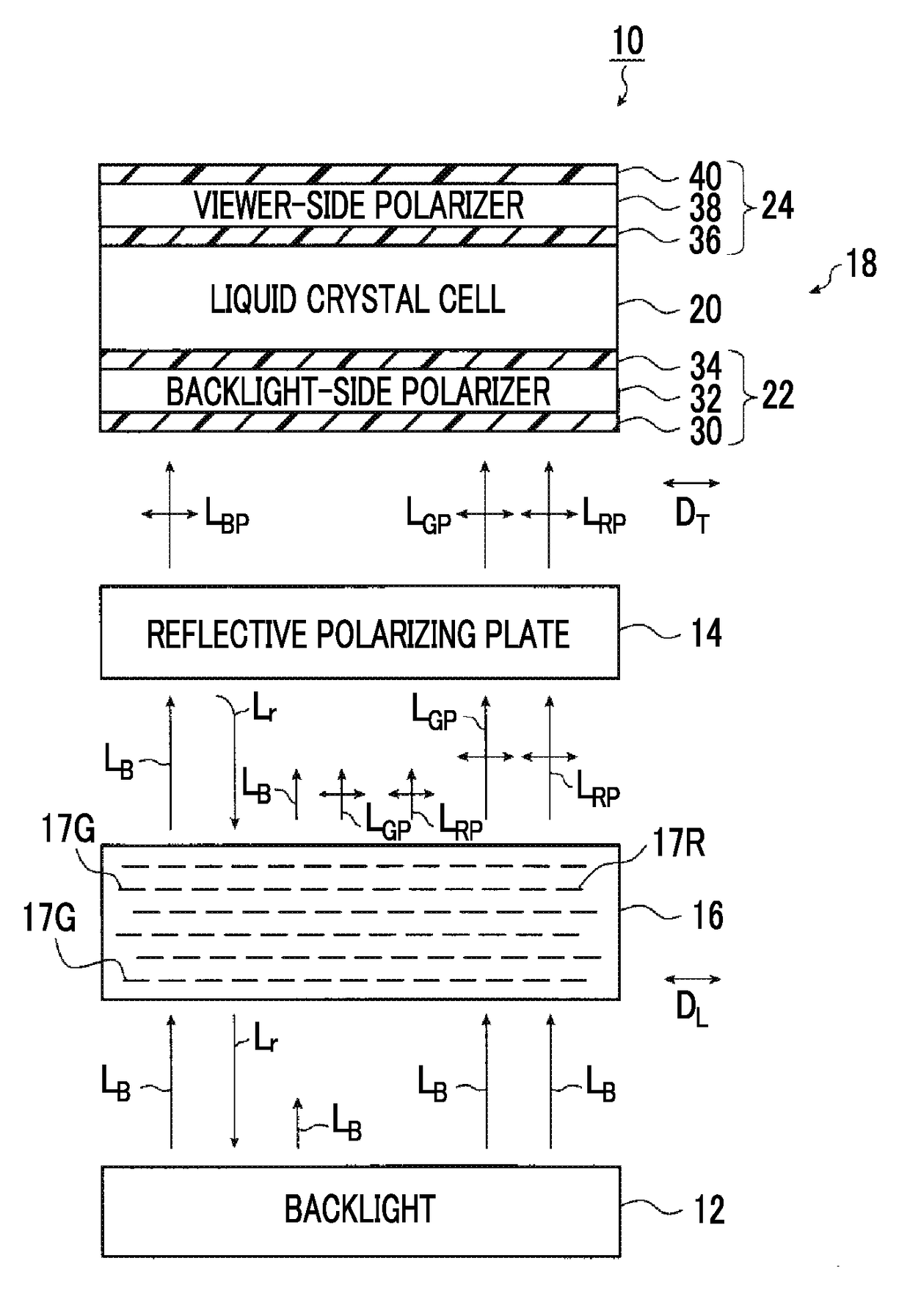
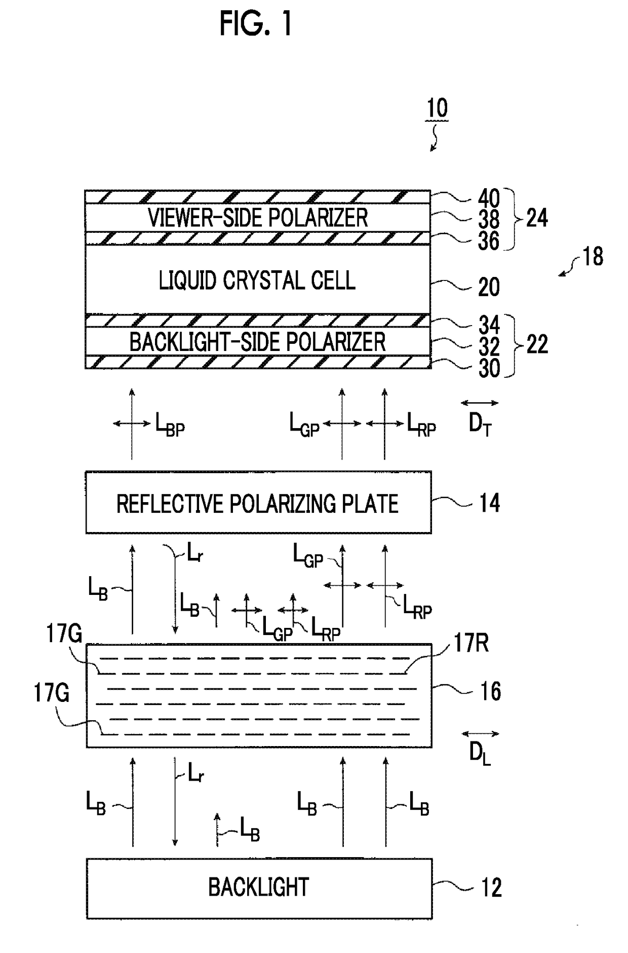
[0201]A commercially available liquid crystal display device (manufactured by Panasonic Corporation, trade name: TH-L42D2) was disassembled, and the backlight unit was changed to the following B narrow-bandwidth backlight unit, thereby producing a liquid crystal display device.

[0202]The B narrow-bandwidth backlight unit used included a blue light emission diode (NICHIA B-LED: Royal Blue, main wavelength: 445 nm, and half-value width: 20 nm) as the light source. In addition, a reflection member that reflected light which has been emitted from the light source and reflected by an optical sheet member is provided at the rear portion of the light source.

[0203]

[0204]As an optical conversion member, with reference to the specification of US2005 / 0211154A, a dissertation (Peng, X. G.; Manna, L.; Yang, W. D.; Wickham, j.; Scher, E.; Kadavanich, and A.; Alivisatos, A. P. Nature 2000, 404, 59 to 61), and a dissertation (Manna, L.; Scher, E. ...

example 2

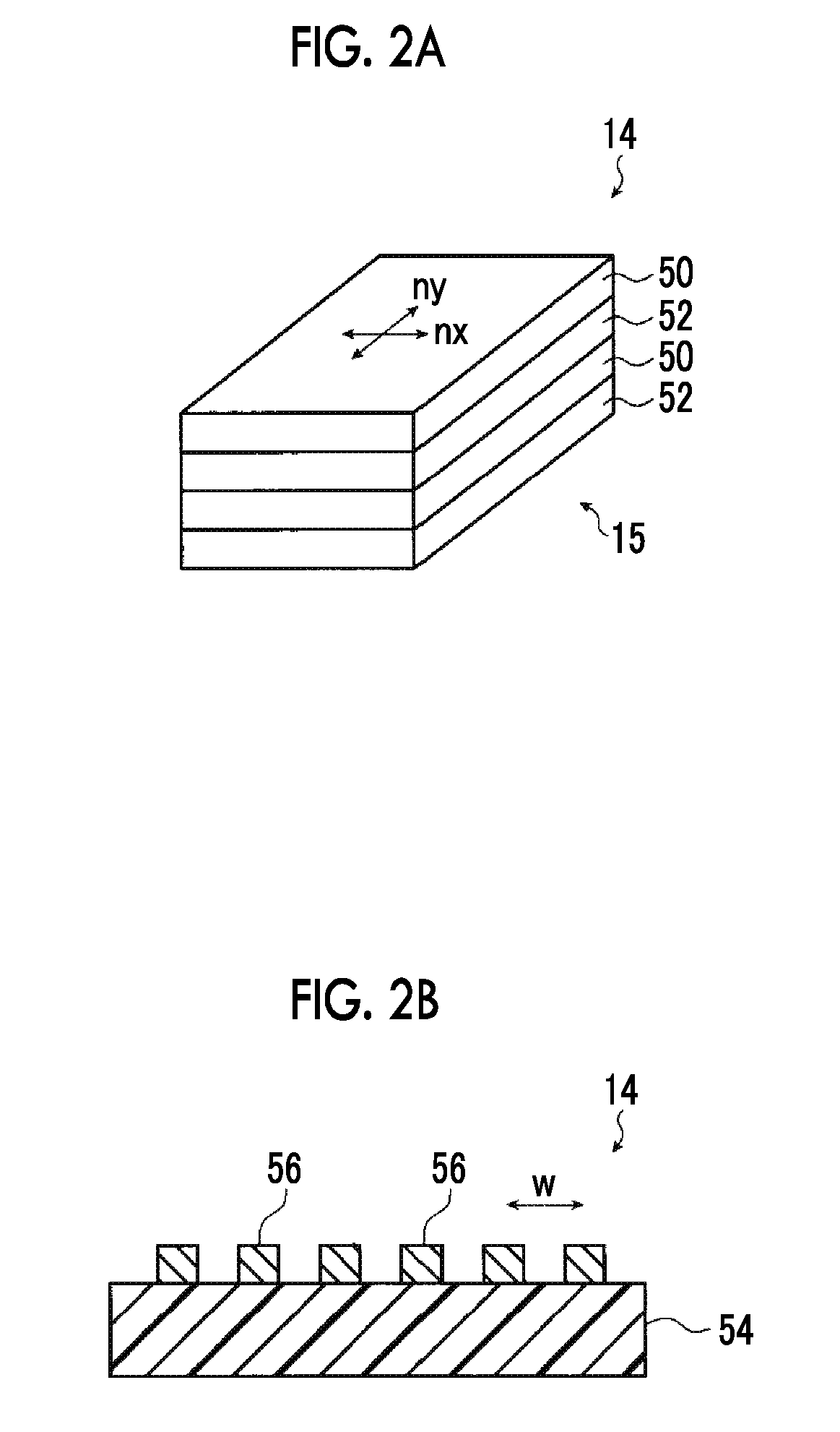
[0214]Example 2 is different from Example 1 that a wire grid-type reflective polarizing plate 2 was provided instead of the reflective polarizing plate 1 and is identical to Example 1 in the other constitutions, and thus detailed description thereof will not be made.

[0215]

[0216]As a reflective polarizing plate 2, with reference to Example 1 in JP2005-195824A, a wire grid polarizing plate was produced.

[0217]

[0218]The reflective polarizing plate was disposed between a backlight and the quantum rod sheet so that the wire direction of the reflective polarizing plate 2 produced above and the transmission axis of the backlight-side polarizing plate were orthogonal to each other, thereby obtaining a liquid crystal display device illustrated in FIG. 10(b).

example 3

[0219]Example 3 is different from Example 1 that a reflective polarizing plate 3 including high-refractive-index layers and low-refractive-index layers was provided instead of the reflective polarizing plate 1 and is identical to Example 1 in the other constitutions, and thus detailed description thereof will not be made.

[0220]

[0221](1) Production of Protective Film

[0222](Preparation of Core Layer Cellulose Acylate Dope 1)

[0223]The following composition was injected into and stirred in a mixing tank, and individual components were dissolved, thereby preparing a core layer cellulose acylate dope 1. The molecular weight of the following compound 1-1 is a weight-average molecular weight computed using gel permeation chromatography (GPC) by means of a method described in Paragraph “0037” of WO2008 / 126535A. That is, for polymers and copolymers, the molecular weights are weight-average molecular weights which are measured by means of gel permeation chromatography (GPC) and are obtained by...


PUM

PropertyMeasurementUnit
specific angleaaaaaaaaaa
angleaaaaaaaaaa

Abstract

Provided is a liquid crystal display device in which color reproducibility and brightness are improved. The liquid crystal display device includes a backlight that emits unpolarized blue light, a quantum rod layer which is provided on an emission side of the backlight and converts some of blue light to red linearly polarized light and green linearly polarized light using multiple quantum rods, a reflective polarizing layer which is provided on a side from which the red linearly polarized light and the green linearly polarized light of the quantum rod layer are emitted, and a liquid crystal panel disposed on a blue linearly polarized light emission side of the reflective polarizing layer, and a long axis direction of the quantum rods in the quantum rod layer and a polarization direction of the blue linearly polarized light emitted from the reflective polarizing layer are parallel to each other.

Description

CROSS-REFERENCE TO RELATED APPLICATIONS[0001]This application is a Continuation of PCT International Application No. PCT / JP2015 / 066336 filed on Jun. 5, 2015, which claims priority under 35 U.S.C. §119(a) to Japanese Patent Application No. 2014-133788 filed on Jun. 30, 2014. The above application is hereby expressly incorporated by reference, in its entirety, into the present application.BACKGROUND OF THE INVENTION[0002]1. Field of the Invention[0003]The present invention relates to a liquid crystal display device in which blue light is used in a backlight and particularly to a liquid crystal display device in which the use efficiency of blue light from the backlight is increased and color reproducibility and brightness are improved.[0004]2. Description of the Related Art[0005]Liquid crystal display devices (hereinafter, also referred to as LCDs) have been used in a range that broadens every year as low-power consumption and space-saving image display devices. Liquid crystal display ...

Claims


Application Information

Patent Timeline
Patent Type & Authority Applications(United States)
IPC IPC(8): G02F1/1335G02F1/13363
CPCG02F1/13362G02F1/133536G02F2001/133614G02F2001/133638G02F1/13363G02F1/13718G02F2202/36G02F1/133548G02F1/133638G02F1/133614
Inventor YANAI, YUJIROSAITOH, YUKITO
Owner FUJIFILM CORP
Why Eureka
Try Eureka