
Wavelength demultiplexer and wavelength multiplexer using same

a wavelength multiplexer and wavelength demultiplexer technology, applied in the field of wavelength multiplexer and wavelength multiplexer using same, can solve the problems of increasing insertion loss, difficult to completely avoid electromagnetic interference (emi) between wireless signals within the cs-dedicated domain, and a large issu

Active Publication Date: 2017-04-27
NAT INST OF INFORMATION & COMM TECH
View PDF27 Cites 4 Cited by
  • Summary
  • Abstract
  • Description
  • Claims
  • Application Information

AI Technical Summary

Benefits of technology

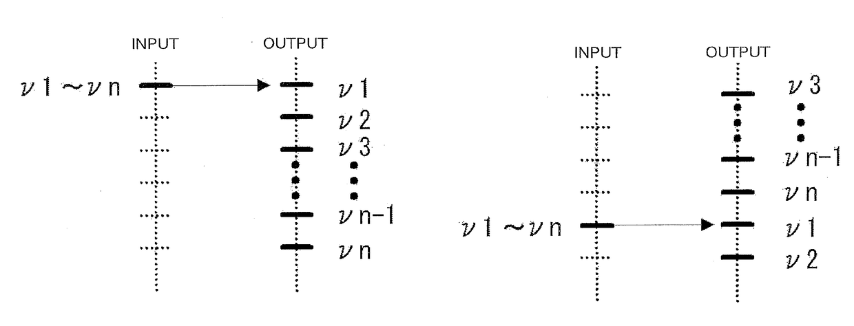
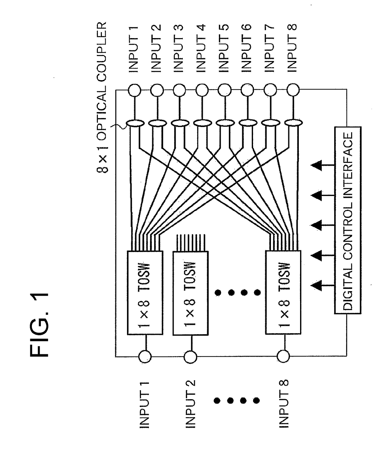
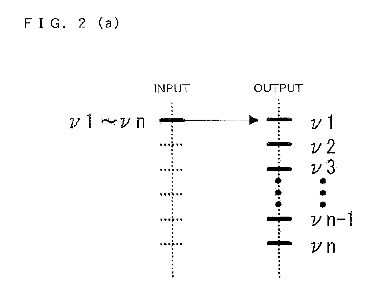
The invention is about a new technology for wavelength demultiplexing that allows for a variable-splitting-ratio switch instead of an optical power splitter. This switch can handle changes in the frequency interval of a radio over fiber signal. By setting the splitting ratio of the switch to 1:1 and allowing for free selection of an input port, the technology can support multiple frequency intervals of the signal. The technical effect of this invention is improved wavelength demultiplexing capabilities for radio over fiber signals.

Problems solved by technology

With the great increase in the demand for wireless access and its communication speed, the way in which mobile traffic is accommodated in cooperation with an optical access network (fixed network) has given rise to an important issue.
Further, also in various wireless systems other than mobile ones (for example, broadcasting, standard radio waves, radar, wireless sensors, etc.), it is unavoidable that the fusion of WDM technology and RoF technology become a key constituent technology for the collection and distribution of wireless signals at a large number of points.
However, such electrical dynamic channel allocation (DCA) makes it difficult to completely avoid electromagnetic interference (EMI) between wireless signals within the CS-dedicated domain.
In this conventional scheme, however, the switching of light paths is performed by repeating two splits, and there is a drawback with regard to the number of channels n in which as the number of channels increases, the splitting loss increases, which results in an increase in insertion loss.
In addition, since the characteristics of the optical coupler used do not include wavelength selectivity, there is no function for collecting multiple optical frequency channel components allocated as desired by using the wavelength division multiplex transmission scheme and for wavelength division multiplexing all the channel components into a single light path.
However, since channel switching is performed for each wavelength, it is difficult to handle RoF signals including multiple wavelength components, signals with optical-frequency-interleaved channels, and the like.

Method used


Image

  • Wavelength demultiplexer and wavelength multiplexer using same
  • Wavelength demultiplexer and wavelength multiplexer using same
  • Wavelength demultiplexer and wavelength multiplexer using same

Examples


example 1

[0032]FIG. 4 illustrates a block diagram of a wavelength demultiplexer of the present invention. In this example, a 16×16-port variable-splitting-ratio matrix optical switch is used as a light path switching device 3. Each element of this optical switch is a thermo-optic switch having a Mach-Zehnder configuration, and the light path switching device 3 is controlled by a controller 4. The output of the light path switching device 3 is input to the ninth to twenty-fourth ports of an AWG of a spectroscopic means 2. To the wavelength demultiplexer, an optical signal obtained by frequency multiplexing a modulated wave and a subcarrier in respective frequency bands which are obtained as a result of division so as to match the channel configuration of the AWG is input.

[0033]This configuration makes it possible to switch the light paths that are input to the spectroscopic means 2, and allows an optical signal extracted for each wavelength from multiple light paths to be obtained in a specif...

example 2

[0042]More specifically, the light path switching device 3 in FIG. 4 is obtained by, for example, forming a Mach-Zehnder interferometer on a PLC (Planar Lightwave Circuit), in which one light path heater is used for heating to change the interference state to form a switch, and is a commercially available product having 16-ch input×16-ch output (NTT Electronics Corporation). In addition, the AWG of the spectroscopic means 2 is that having 32-ch input×40-ch output with a channel spacing of 25 GHz. The transmission spectrum of a flat-top type is desirable, and, for example, the 1-dB bandwidth is greater than or equal to 9.3 GHz for a wavelength of 1556.353 to 1548.509 nm (0.2 nm / ch), which accounts for 37% of the channel spacing.

example 3

[0043]A wavelength-multiplexed signal can be obtained by inputting, from the output side of the wavelength demultiplexer described above, a modulated wave and a subcarrier in respective frequency bands obtained as a result of division so as to match the channel configuration of the AWG and by outputting them from the input side of the light path switching device. That is, the wavelength demultiplexer described above operates as a wavelength multiplexer.


PUM


Abstract

A wavelength demultiplexer is equipped with a spectroscopic means (which separates light that is input from multiple input light paths, and outputs the light to multiple output light paths) and a light path switching device (a device that switches the light paths that are input to the spectroscopic means, with the switching being performed by an external operation), and the light path switching device may be a device that distributes the input from one input port to multiple output ports. The light path switching device and the spectroscopic means are polarization-independent, with the input light paths, the output light paths, and the light paths between the light path switching device and the spectroscopic means being polarization-maintaining light paths, so the relative polarization configuration is the same for the input light and the output light.

Description

TECHNICAL FIELD[0001]The present invention relates to a wavelength demultiplexer applicable to wavelength multiplexing technology used in radio over fiber technologies and a wavelength multiplexer using the same.BACKGROUND ART[0002]Radio over fiber (RoF) networks for radio waves in the millimeter-wave frequency band are expected as a future infrastructure technology because an effective increase in the coverage of wireless access networks that use the radio waves is possible. Additionally, wavelength division multiplexing (WDM) technology is very attractive since in millimeter-wave frequency band RoF networks, the device configuration of a remote access unit (RAU) having an antenna disposed therein is simplified to minimize cost and power consumption and a remote node (RN) having a function of multiplexing and demultiplexing WDM signals is capable of widely distributing RoF signals to a large number of RAUs. Accordingly, millimeter-wave frequency band RoF networks that use WDM techn...

Claims


Application Information

Patent Timeline
IPC IPC(8): H04Q11/00H04J14/06G02B6/293H04B10/2575
CPCH04Q11/0005H04B10/2575H04J14/06G02B6/29397H04Q2011/002H04Q2011/0035H04Q2213/017H04Q2011/0032G02B6/2938H04J14/02
Inventor KURI, TOSHIAKI
Owner NAT INST OF INFORMATION & COMM TECH
Learn More