
Energy recovery system

Active Publication Date: 2017-05-04
EBARA CORP
View PDF2 Cites 1 Cited by
  • Summary
  • Abstract
  • Description
  • Claims
  • Application Information

AI Technical Summary

Benefits of technology

The present invention provides a system that can recover energy from pressurized water and use it to produce high-pressure water. A turbine is used to compensate for pressure loss caused by the reverse-osmosis membrane, pipes, and control valves in the energy recovery device. This ensures a self-regulating process that can adapt to changes in environmental conditions. The technical effect is to improve the efficiency of the system and reduce energy waste.

Problems solved by technology

More than half of electric power expense which is the largest operational cost in the seawater desalination plant is consumed for pressurizing the seawater by the high-pressure pump.
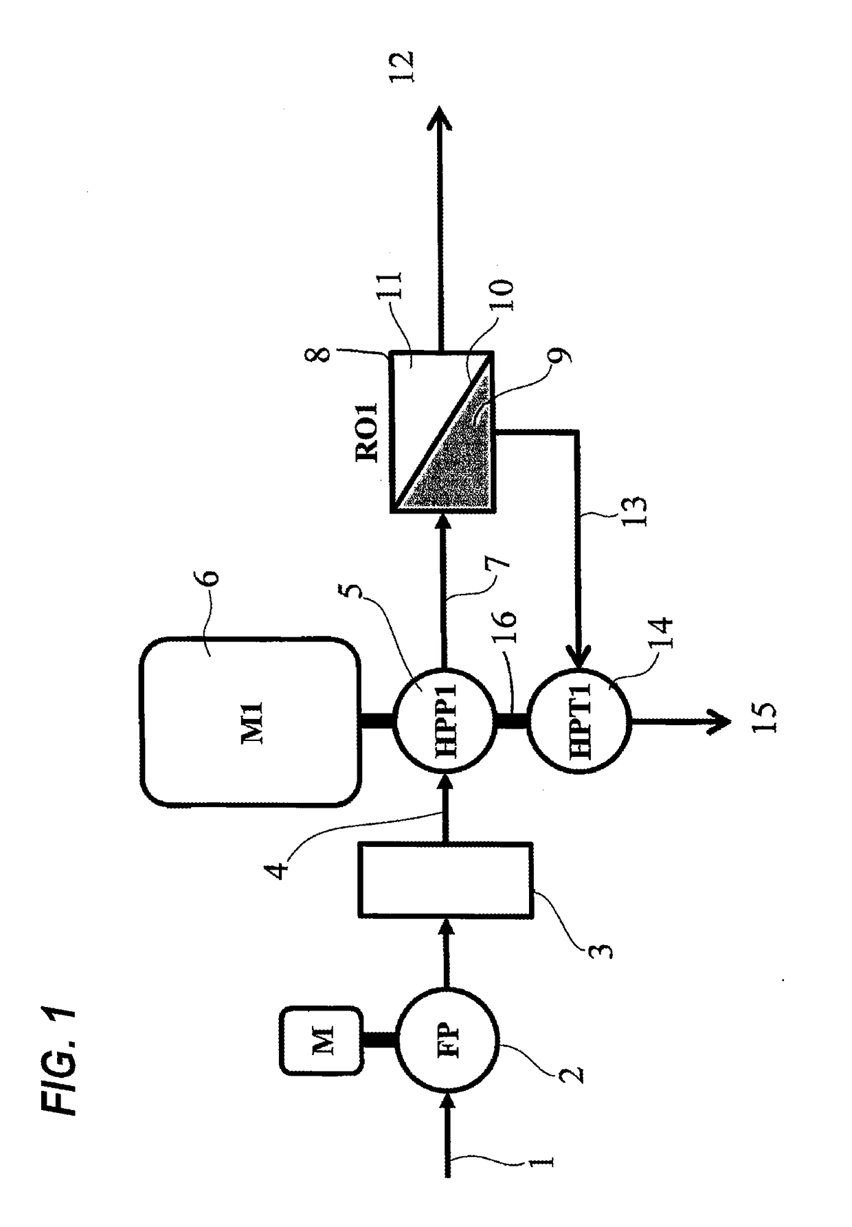
Thus, this system is problematic in that even if the efficiency of the turbine and the efficiency of the high-pressure pump are 90% each, the overall energy recovery efficiency becomes low because the overall energy recovery efficiency is expressed by multiplication of both efficiencies (90%×90%=81%).
Further, because the pump impeller and the turbine runner are disposed coaxially with each other, it is difficult to operate the turbine under optimum conditions at all times while following a change in operating conditions, resulting in a further efficiency reduction.
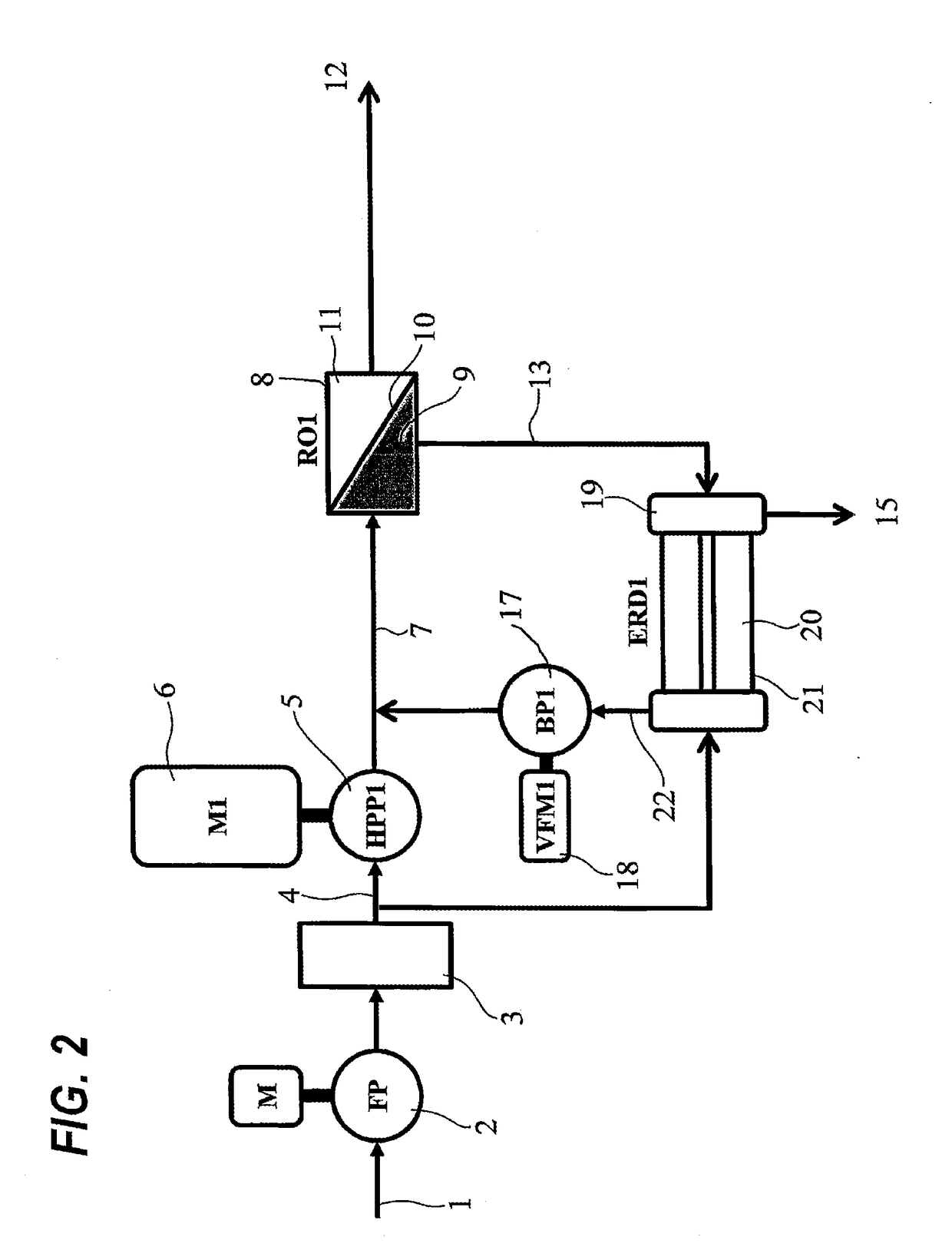
Because the suction pressure of the booster pump is nearly as high as the discharge pressure of the high-pressure pump and becomes a high-pressure condition, the booster pump is disadvantageous in that a pump having a special seal structure is required.

Method used


Image

  • Energy recovery system
  • Energy recovery system
  • Energy recovery system

Examples


Embodiment Construction

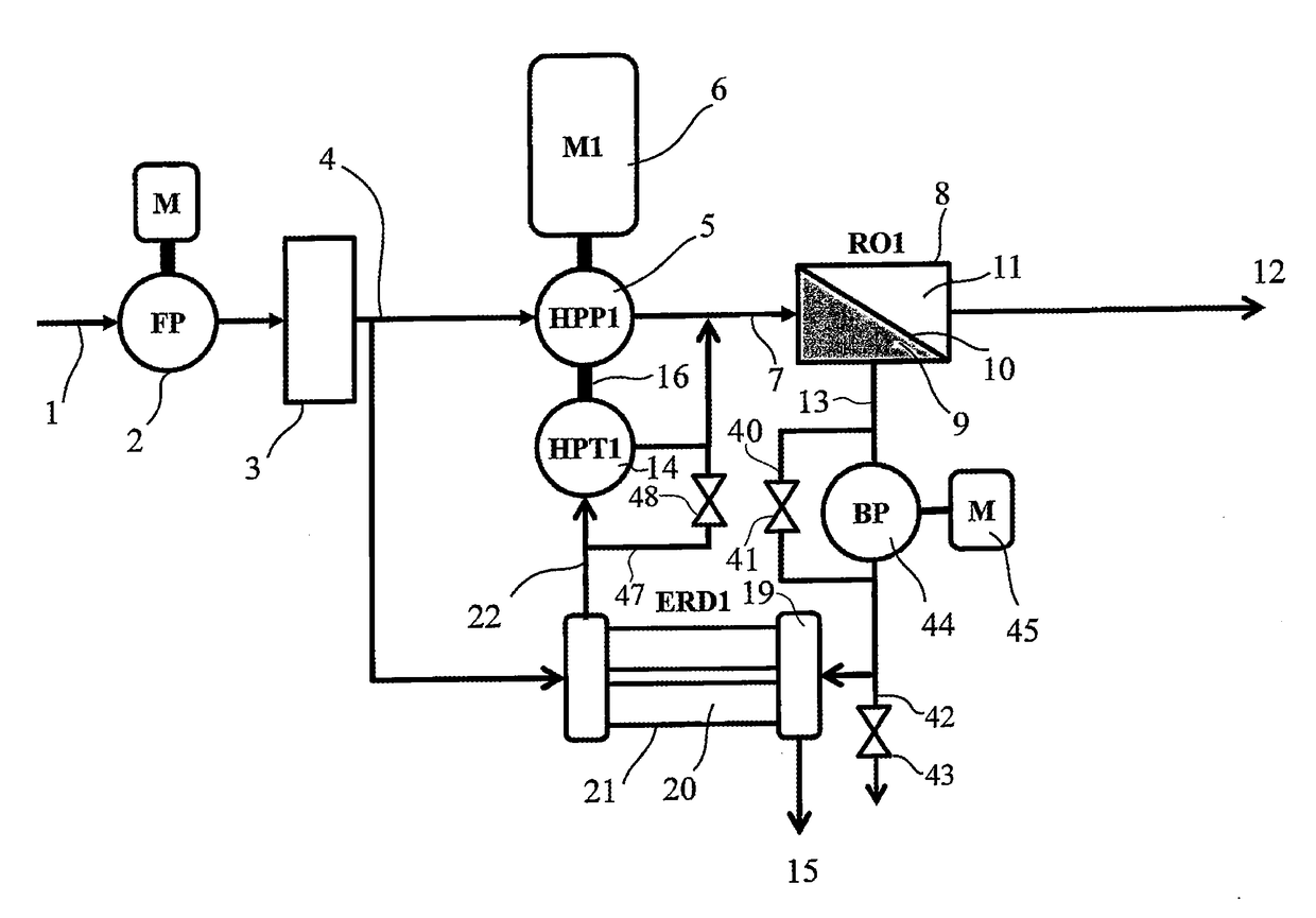
[0035]An energy recovery system according to a preferred embodiment of the present invention will be described below with reference to FIG. 3. The seawater 1 that has been supplied to the system by a feed pump 2 is processed to have certain water qualities by a pretreatment system 3, and is then pressurized by a high-pressure pump 5 driven by an electric motor 6 and delivered via a high-pressure line 7 into a reverse-osmosis membrane cartridge 8. Part of the seawater in a high-pressure chamber 9 of the reverse-osmosis membrane cartridge passes through a reverse-osmosis membrane 10 against the osmotic pressure and is desalinated, and desalinated water 12 is taken out from a low-pressure chamber 11. The remaining seawater becomes in a concentrated state of a high salinity and is discharged as a concentrated reject from the reverse-osmosis membrane cartridge 8 to a reject line 13. The reject is further pressurized by a booster pump 44 driven by an electric motor 45, and then the pressu...


PUM


Abstract

An energy recovery system in a seawater desalination plant uses a reverse-osmosis membrane method for removing salinity from seawater. The system is configured to supply high-pressure water produced by pressurizing raw water with a high-pressure pump to a reverse-osmosis membrane cartridge, and to supply concentrated water discharged from the cartridge to an isobaric energy recovery device to recover pressure energy of the concentrated water whereby part of the raw water supplied to the isobaric energy recovery device is pressurized, and then to allow the pressurized raw water to merge into the high-pressure water pressurized by the high-pressure pump. The system includes a booster pump for boosting a pressure of the concentrated water discharged from the cartridge, and an energy recovery turbine for recovering energy by using the pressure head difference between the pressurized raw water from the isobaric energy recovery device and the high-pressure water discharged from the pump.

Description

TECHNICAL FIELD[0001]The present invention is particularly preferable for use as an energy recovery system serving as a consumption energy reduction means in a seawater desalination plant which uses a reverse-osmosis membrane method for removing salinity from seawater.BACKGROUND ART[0002]A seawater desalination plant which employs a reverse-osmosis membrane method is composed mainly of a pretreatment system, a high-pressure pump, a reverse-osmosis membrane cartridge, and an energy recovery system. In the seawater desalination plant, the intake seawater is processed to have certain water qualities by the pretreatment system, and the pretreated seawater is delivered into the reverse-osmosis membrane cartridge under pressure by the high-pressure pump. Part of the high-pressure seawater in the reverse-osmosis membrane cartridge passes through the reverse-osmosis membrane against the osmotic pressure and is desalinated, and fresh water is taken out from the reverse-osmosis membrane cartr...

Claims


Application Information

Patent Timeline
IPC IPC(8): B01D61/06F01D15/08F03B13/00B01D61/02C02F1/44
CPCB01D61/06B01D61/025C02F1/441F03B13/00F01D15/08B01D2313/246F05B2220/32B01D2313/44B01D2317/02C02F2103/08C02F2201/006C02F2303/10B01D2313/243C02F2301/08F04B23/00F05B2220/62Y02E10/30Y02W10/30Y02A20/131F01L15/08Y02E10/20
Inventor GOTO, AKIRATAKITA, SHIGEO
Owner EBARA CORP
Learn More