Zero emission power plant with co2 waste utilization

a waste and power plant technology, applied in the direction of reciprocating piston engines, chemical/physical/physico-chemical stationary reactors, energy input, etc., can solve the problems of fuel cell systems, judged according to their operational principles, and inability to meet large-scale goals, so as to achieve the effect of eliminating co2 emissions and double carbon credits

Inactive Publication Date: 2017-05-11
ZTEK
View PDF11 Cites 12 Cited by
  • Summary
  • Abstract
  • Description
  • Claims
  • Application Information

AI Technical Summary

Benefits of technology

[0006]The present application provides a clean energy system, a renewable energy system or a zero emission energy system (ZEES) with CO2 waste utilization. This application utilizes chemical principles for concurrent power generation and energy conversion to eliminate CO2 emissions from power plants and introduce new sources of liquid fuel for transportation. The energy system provided in the present application solves the two most serious problems in the current energy industry: petro-fuel shortage and global warming due to greenhouse gas (GHG) emissions. In one embodiment, the clean energy system is a zero emission energy system when a carbon containing stream with a matched amount of H2 is used for liquid fuel production and H2 alone is used for power generation. When employing a renewable feedstock, the energy system constitutes negative CO2 footprints thus potentially gaining double carbon credits.
[0007]According to one practice of the present invention, clean power is generated and any greenhouse gas (GHG) produced by the system is retained and employed to help produce high valued fuels. The energy system provided in the present application may be properly sized for any installation, converting available municipal solid waste (MSW) or biomass into clean energy at affordable costs and with low carbon footprints. The energy system may be applied equally to feedstock including coal and other solid hydrocarbon fuels.
[0011]According to the teachings of the present invention, the clean energy system may be operated to maximize the use of carbon for the production of a) liquid bio-fuels, including methanol, ethanol, propanol and butanol, as well as b) liquid synfuels, including DME, gasoline, propane, butane, jet fuel and diesel. The energy reactor utilizes chemical-catalysts or bio-catalysts. The energy reactor may be a chemical-catalyst bed, such as a fixed bed, structured bed, slurry bed or microchannel with integrated heat exchanger. The energy reactor may employ single functional catalysts, bifunctional catalysts or multi-functional catalysts to achieve improved performances. The energy reactor may employ bio-catalysts including varieties of yeasts, bacteria and enzymes.

Problems solved by technology

However, it is reported that the goals are unlikely to be met by a large margin unless revolutionary technologies are developed in the near future.
Fuel cell systems, judged according to their operational principles, do not have renewable characteristics.

Method used


Image

  • Zero emission power plant with co2 waste utilization
  • Zero emission power plant with co2 waste utilization
  • Zero emission power plant with co2 waste utilization

Examples


Embodiment Construction

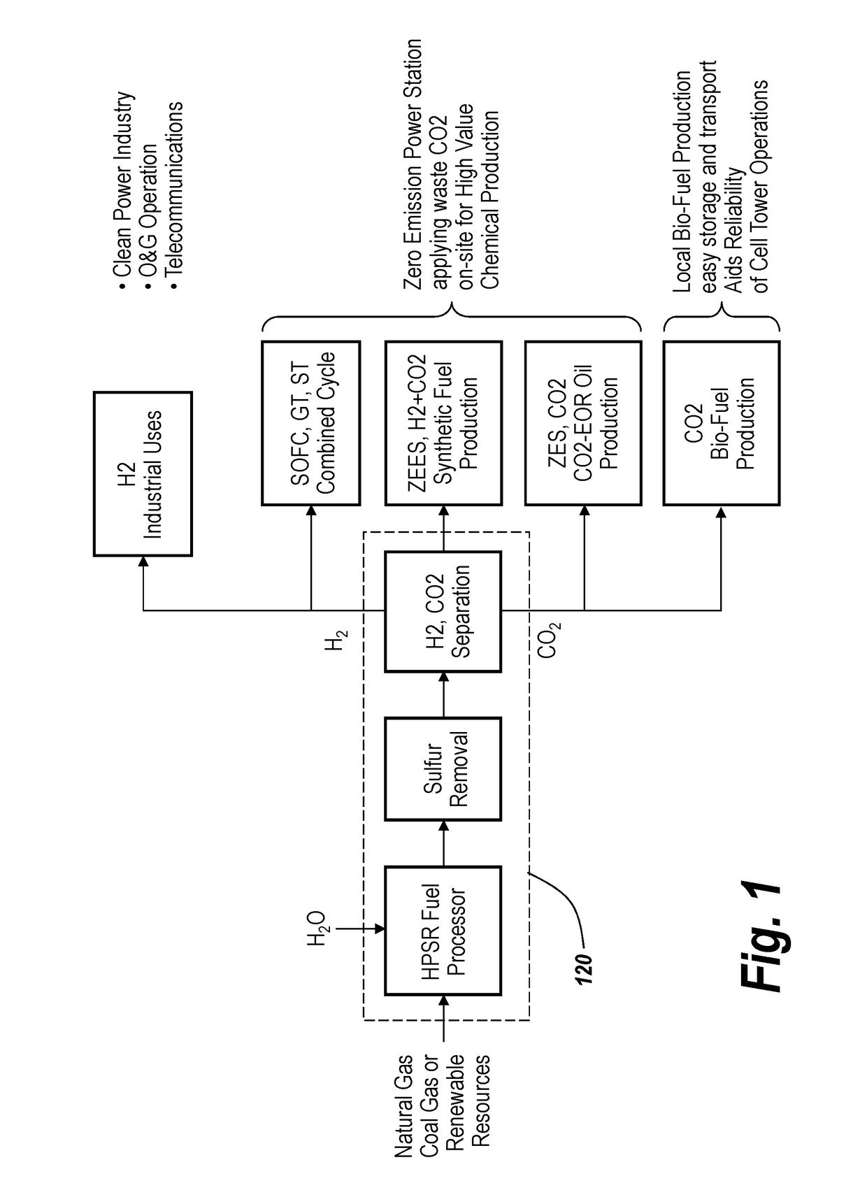
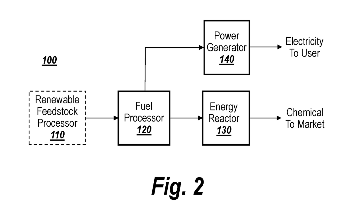
[0026]FIG. 1 is a block diagram illustrating clean technology applications including the embodiments provided in the present application. A fuel processor 120 may receive natural gas, coal gas or renewable gas and process the gas to produce, H2, CO2 and / or a mixture of H2 and CO2. A sulfur component may be removed, and H2 and CO2 may be separated.

[0027]The produced H2 may be used for a solid oxide fuel cell (SOFC) system. Fuel cells produce clean exhaust without SOx or NOx through an electrochemical process rather than a thermodynamic process as used in traditional combustion systems. The SOFC also has an advantage in that its clean exhaust remains at a high temperature, which is suitable to drive a traditional system for additional power generation. The overall exhaust remains clean while the power output or the system efficiency doubles.

[0028]The SOFC may be integrated with heating, ventilation and air conditioning (HVAC) systems to perform functions for human comfort using the ho...


PUM

PropertyMeasurementUnit
temperatureaaaaaaaaaa

Abstract

A clean energy system, a renewable energy system or a zero emission energy system (ZEES) to utilize CO2 waste. The energy system may include a fuel processor, an energy catalytic reactor, and a power generator. The fuel processor may catalytically convert the CH4 component in the natural gas, biogas or syngas into a reformate including H2, CO, CO2 and H2O species. The energy reactor may convert the reformate in gas form into a liquid fuel. The power generator may generate power using an output of the fuel processor and / or an output of the energy reactor.

Description

RELATED APPLICATION[0001]This application is a Continuation application of U.S. application Ser. No. 14 / 115,231 filed Jan. 24, 2014, which is a 371 national phase application of International Application PCT / US2012 / 036640 filed May 4, 2012, which claims priority to U.S. Provisional Application Nos. 61 / 635,176 filed Apr. 18, 2012, 61 / 482,495 filed May 4, 2011, and 61 / 515,900 filed Aug. 6, 2011, the contents of which are hereby incorporated by reference.BACKGROUND OF THE INVENTION[0002]This application relates to a clean energy system, a renewable energy system or a zero emission energy system (ZEES), and more particularly to a chemical principle based power plant (CPPP) with CO2 waste utilization.[0003]The governmental efforts to curb greenhouse gas (GHG) emissions have been relying on the laws of individual countries and states for some time now. In general, most countries and states share the interim goal of reducing GHG emissions to 25% below 1990 levels by 2020, and an overall go...

Claims


Application Information

Patent Timeline
Patent Type & Authority Applications(United States)
IPC IPC(8): F01B21/04C01B3/48C07C41/09B01J19/24C10G2/00C07C29/152C01B3/38C01B3/56
CPCF01B21/04B01J2219/24C01B3/386C01B3/48C01B3/56B01J19/245B01J19/249C10G2/32C07C29/152C07C41/09C01B2203/0261C01B2203/0244C01B2203/0233C01B2203/0283C01B2203/042C01B2203/0495C01B2203/047C01B2203/0475C01B2203/061C01B2203/0833C01B2203/1241C01B2203/84C01B3/38B01J19/0093C10K1/004C10K1/005C10K1/04C10K1/32C10K3/04C01B2203/043C01B2203/0485C01B2203/066C01B2203/1258C01B2203/146C01B2203/86Y02T50/678B01J2219/2479B01J2219/2465B01J2219/2474B01J2219/00783B01J2219/00835B01J2219/00873C10J2300/0916C10J2300/092C10J2300/0946C10J2300/1665C10J2300/1671Y02E50/10Y02E50/30Y02P20/145Y02P20/133Y02P30/00
Inventor HSU, MICHAEL S.
Owner ZTEK
Why Eureka
Try Eureka