Method and apparatus for monitoring and determining energy storage device characteristics using fiber optics
- Summary
- Abstract
- Description
- Claims
- Application Information
AI Technical Summary
Benefits of technology
Problems solved by technology
Method used
Image
Examples
first embodiment
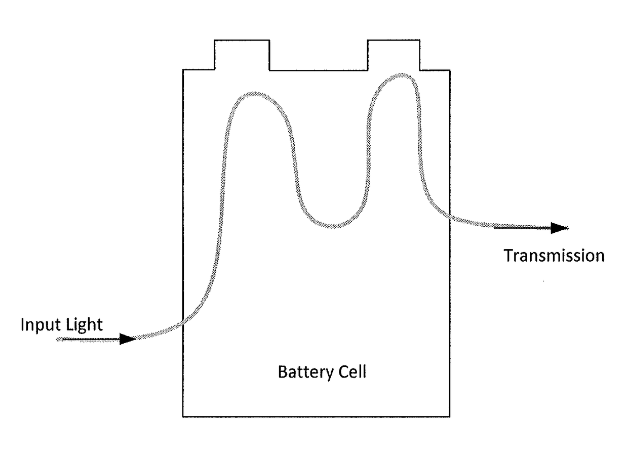
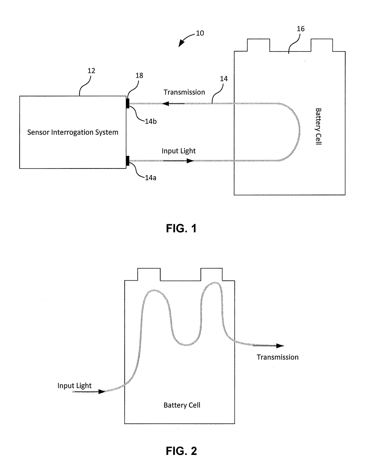
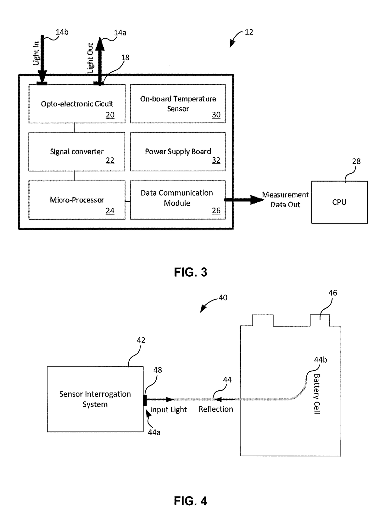
[0045]Turning to FIG. 1, a schematic diagram of a system for energy storage device characteristic monitoring is shown. In this embodiment, which may be seen as a transmission mode sensing embodiment, the apparatus, or system, 10 includes a sensor interrogation system 12 which is connected to both ends of an optical fiber cable 14 which has a portion of the cable embedded within an energy storage device, such as a battery cell 16. One end of the optical fiber cable 14 may be seen as a light output end 14a and the other end may be seen as a light input end 14b. The embodiment may be seen as a transmission mode sensing embodiment since both ends of the optical fiber cable 14 are connected to the sensor interrogation system 12 such that light is transmitted out of the light output end 14a through the optical fiber cable 14 and then returned through the light input end 14b. FIG. 2 is a schematic diagram of another embodiment of how the optical fiber cable 14 may be embedded within the ba...
second embodiment
[0055]Turning to FIG. 4, a schematic diagram of a system for energy storage device characteristic monitoring is shown. In this embodiment, the system 40 includes a sensor interrogation system 42 which is connected to one end of an optical fiber cable 44. In the current embodiment, the end connected to the sensor interrogation system may be seen as the light input end and the light output end 44a. A portion of the optical fiber cable 44 (along with a second end 44b of the cable 44) is embedded within an energy storage device, such as a battery cell 46. Further detail with respect to the embedding of the cable within the battery cell 46 Will be described below. In use, light is transmitted from the sensor interrogation system 42 through the optical fiber cable 44 and then reflected back towards the sensor interrogation system 42 when it reaches the second end of the cable. FIG. 5 is another embodiment of how the optical fiber cable 44 may be embedded within the battery cell 46.
[0056]T...
PUM
 Abstract
Description
Claims
Application Information
 - R&D
- Intellectual Property
- Life Sciences
- Materials
- Tech Scout
- Unparalleled Data Quality
- Higher Quality Content
- 60% Fewer Hallucinations
Browse by: Latest US Patents, China's latest patents, Technical Efficacy Thesaurus, Application Domain, Technology Topic, Popular Technical Reports.
© 2025 PatSnap. All rights reserved.Legal|Privacy policy|Modern Slavery Act Transparency Statement|Sitemap|About US| Contact US: help@patsnap.com


