
Razor blade

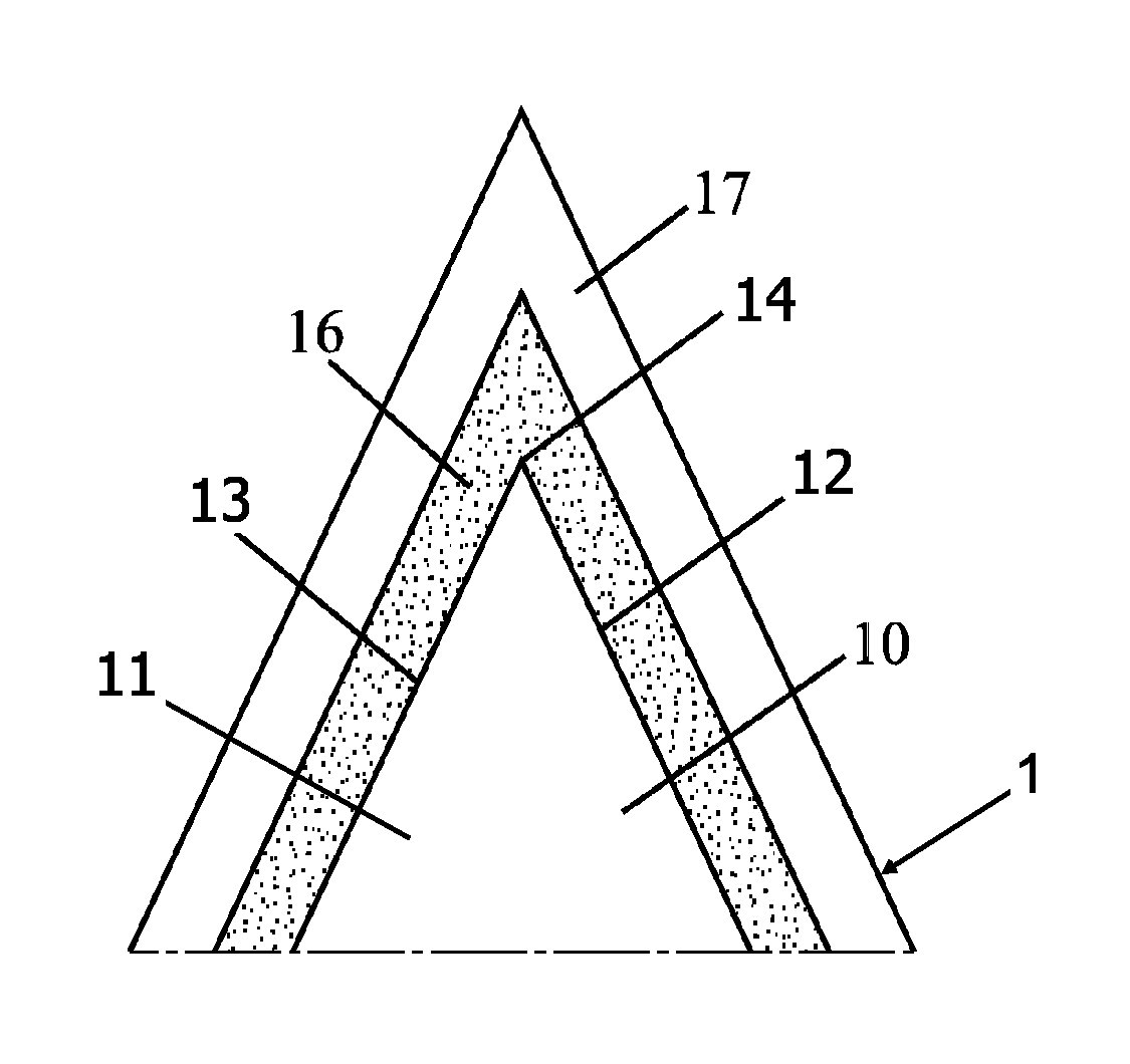
a technology of razor blades and blades, applied in the field of razor blade edges, can solve the problems of affecting shaving comfort, increasing the risk of breakage or damage, and reducing so as to reduce the thickness of the blade substrate, and increase the hardness value of the strengthening coating layer

Active Publication Date: 2017-05-18
BIC VIOLEX SA
View PDF6 Cites 13 Cited by
  • Summary
  • Abstract
  • Description
  • Claims
  • Application Information

AI Technical Summary

Benefits of technology

The present invention is about a shaving razor that includes a blade substrate with a coating that is strengthened through a physical vapor deposition process. The strengthening coating layer is deposited on the blade edge substrate and has increased hardness, which allows for a decreased thickness of the blade substrate with coating. This results in a blade that is stronger and more durable. The strengthening coating layer has an altered configuration with small crystallites and a density of >4.15 g / cm3, which provides increased strength and durability for the blade edge substrate portion. Overall, this patent provides a shaving razor with improved performance.

Problems solved by technology

If the blade tip is robust, it will enable less wear and a longer service life, but it would result in larger cutting forces, which adversely affect the shaving comfort.
A thin blade tip profile leads to less cutting forces, but also to an increase in risk of breakage or damage, and a shorter service life.
First, because the razor blade substrate edge has a very peculiar geometry, depositing a coating on it which would operate as a suitable coating by enhancing the cutting properties and strengthening the razor blade edge is very difficult.
Second, razor blades are a mass consumption good, so the coatings must be uniformly applied from product to product, and at a high throughput, which requires a coating compatible with a very reliable process.
Third, even if it were possible to deposit a new coating on a razor blade, measuring the improvement with respect to conventional razor blades is also very difficult.
This difficulty is because the perceived quality of shaving by test panels can be very subjective.

Method used


Image

  • Razor blade
  • Razor blade
  • Razor blade

Examples


Embodiment Construction

[0038]It is to be understood that the present inventive concept is not limited in its application to the details of construction and to the embodiments of the components set forth in the following description or illustrated in the drawings. The figures and written description are provided to teach any person skilled in the art to make and use the inventions for which patent protection is sought. The present inventive concept is capable of other embodiments and of being practiced and carried out in various ways. Persons of skill in the art will appreciate that the development of an actual commercial embodiment incorporating aspects of the present inventive concept will require numerous implementations—specific decisions to achieve the developer's ultimate goal for the commercial embodiment. While these efforts may be complex and time-consuming, these efforts, nevertheless, would be a routine undertaking for those of skill in the art of having the benefit of this disclosure.

[0039]I. T...


PUM

PropertyMeasurementUnit
thicknessaaaaaaaaaa
thicknessaaaaaaaaaa
thicknessaaaaaaaaaa

Abstract

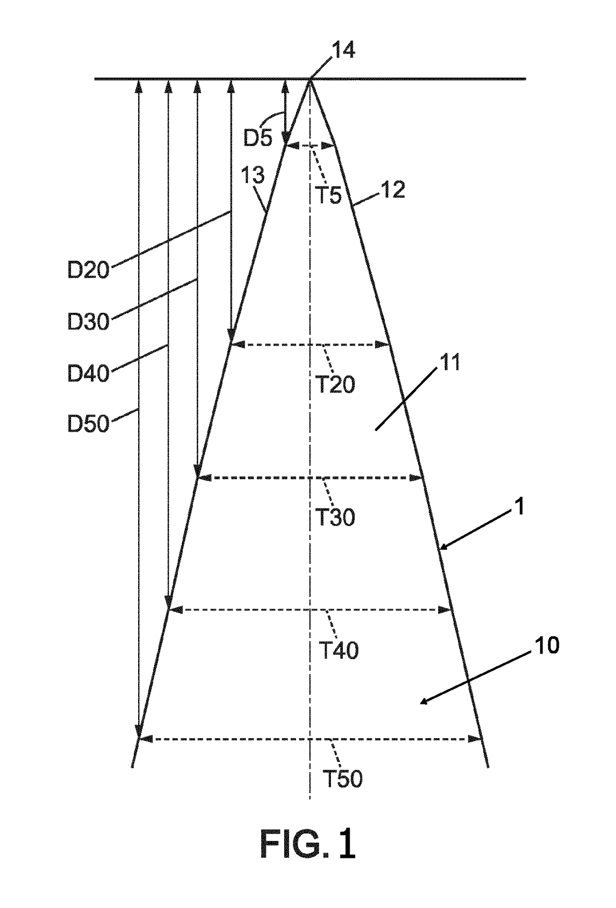
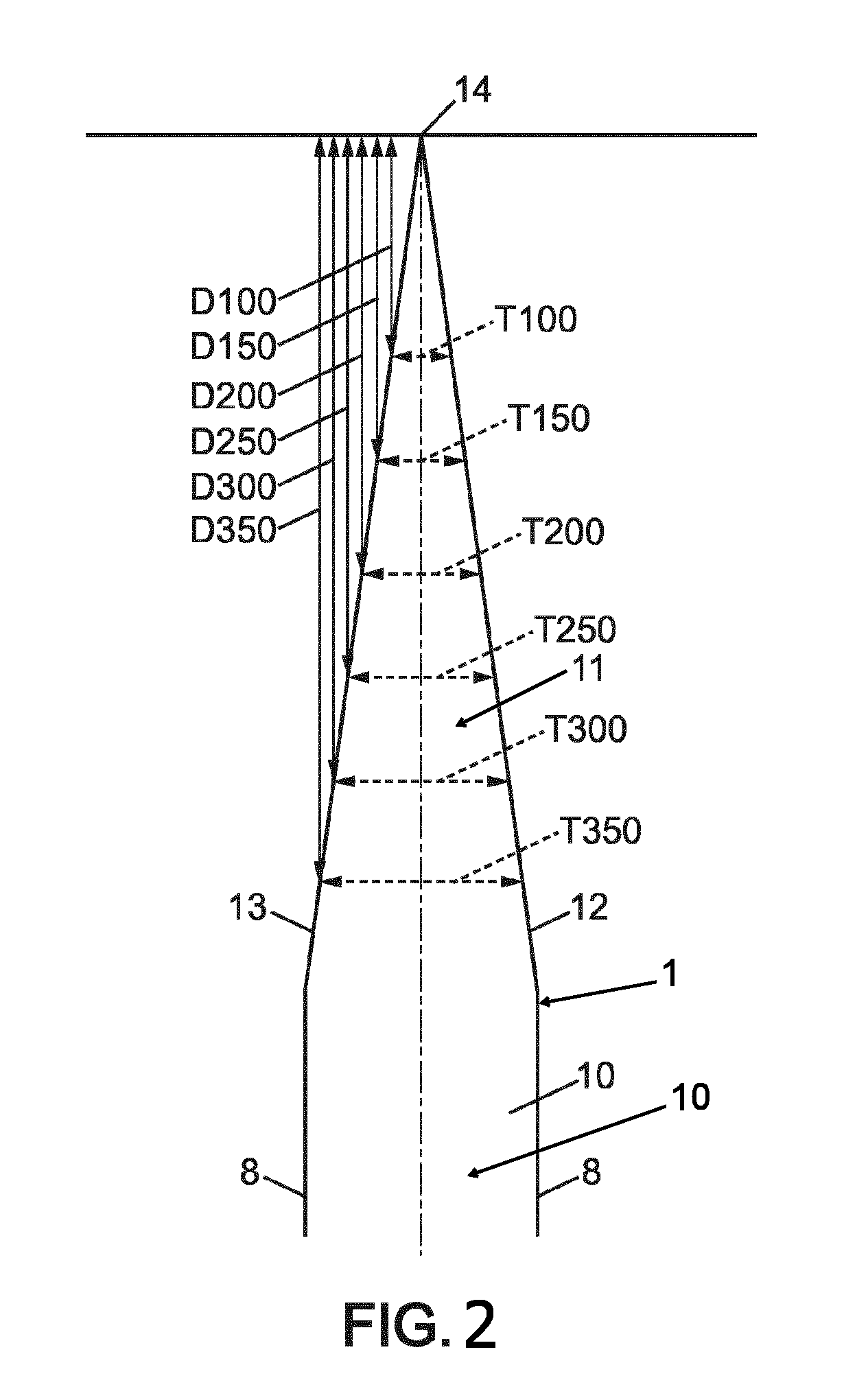
A razor blade comprising a blade substrate with a blade edge substrate portion ending in blade tip. The razor blade is covered by a strengthening coating deposited on the blade edge substrate portion via a deposition process. The deposition process causes a hardness value of the strengthening coating layer to be increased, which, among other factors, allows for a decreased thickness of the blade substrate with coating. The blade substrate with coating has (i) a thickness of between about 1.57 and 2.37 micrometers measured at a distance of about five micrometers from the coating tip, (ii) a thickness of between about 4.62 and 6.74 micrometers measured at a distance of about twenty micrometers from the coating tip, and (iii) a thickness of between about 19.82 and 27.52 micrometers measured at a distance of about one hundred micrometers from the coating tip.

Description

CROSS-REFERENCE TO RELATED APPLICATIONS[0001]This Patent Application claims priority to and is a continuation in part of PCT / EP2015 / 067477 filed Jul. 30, 2015; PCT / EP2014 / 079091 filed Dec. 22, 2014 and PCT / EP2014 / 066511 filed Jul. 31, 2014; the entire contents of which are herein incorporated by reference in their entireties.BACKGROUND OF THE INVENTION[0002]1. Field of the Invention[0003]The present inventive concept relates to razor blades and more particularly to razor blade edges and razor blade coatings.[0004]2. Description of the Related Art[0005]From the prior art, razor blades have been provided. Suitably placed in a razor cartridge, they offer the ultimate function of cutting hair or shaving. A shape of the razor blade and a coating of the razor blade play an important role in the quality of the shaving.[0006]Regarding shape, razor blades typically have a continuously tapering shape converging toward an ultimate tip. The portion of the razor blade which is closest to the ult...

Claims


Application Information

Patent Timeline
Patent Type & Authority Applications(United States)
IPC IPC(8): B26B21/60B26B21/22C23C14/02C23C14/14C23C14/06B26B21/40C23C14/34
CPCB26B21/60B26B21/4068B26B21/22C23C14/021C23C14/14C23C14/067C23C14/3464B05D1/60B05D3/0254B05D3/0493B05D5/08B05D7/14B05D7/51B05D2202/15B05D2350/63B05D2350/65B05D2401/33
Inventor SIOZIOS, ANASTASIOSMAVROEIDIS, KONSTANTINOSKONTOKOSTAS, LABROSPAPATRIANTAFYLLOU, IOANNISTERLILIS, TAXIARCHIS
Owner BIC VIOLEX SA
Learn More