
Delayed coking process with pre-cracking reactor

Active Publication Date: 2017-05-25
INDIAN OIL CORPORATION
View PDF6 Cites 4 Cited by
  • Summary
  • Abstract
  • Description
  • Claims
  • Application Information

AI Technical Summary

Benefits of technology

The present invention improves the production of valuable products and reduces the production of low value coke. This results in higher overall yields of desired products.

Problems solved by technology

A major disadvantage of the existing delayed coking unit is the high yield of low value coke as the product.

Method used


Image

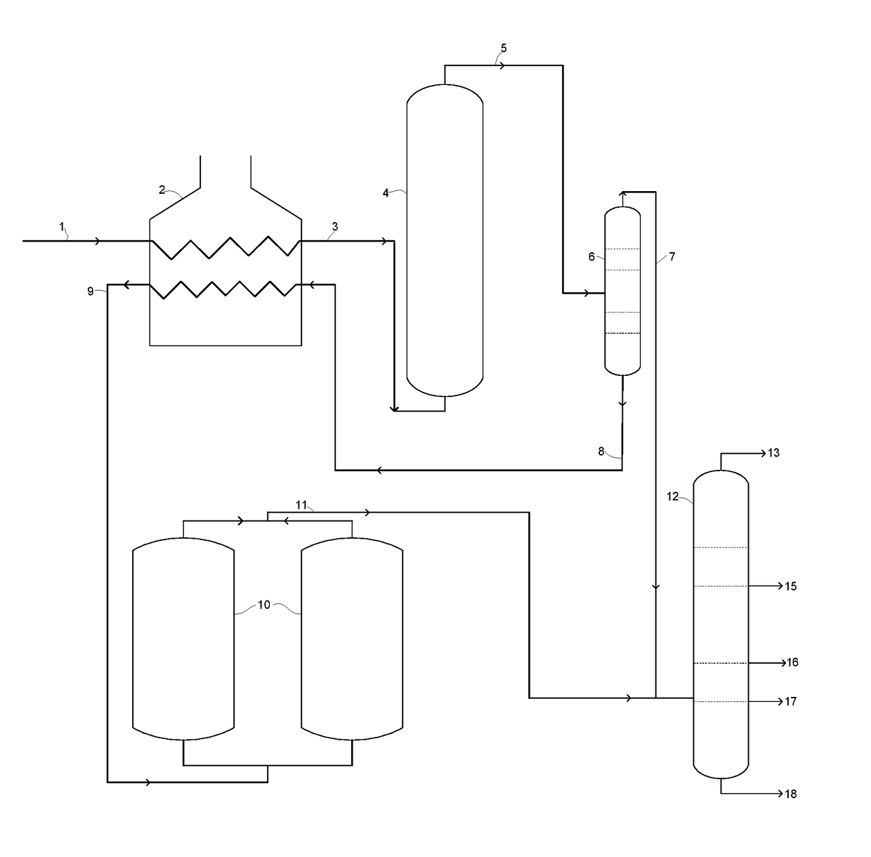
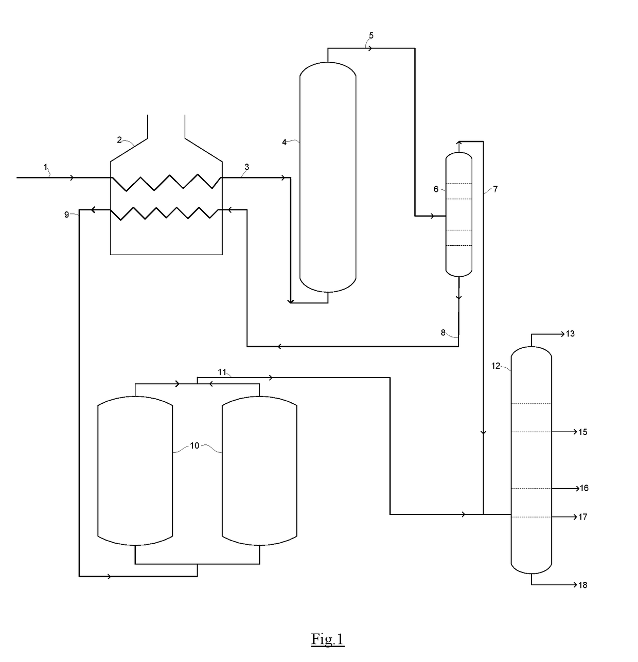
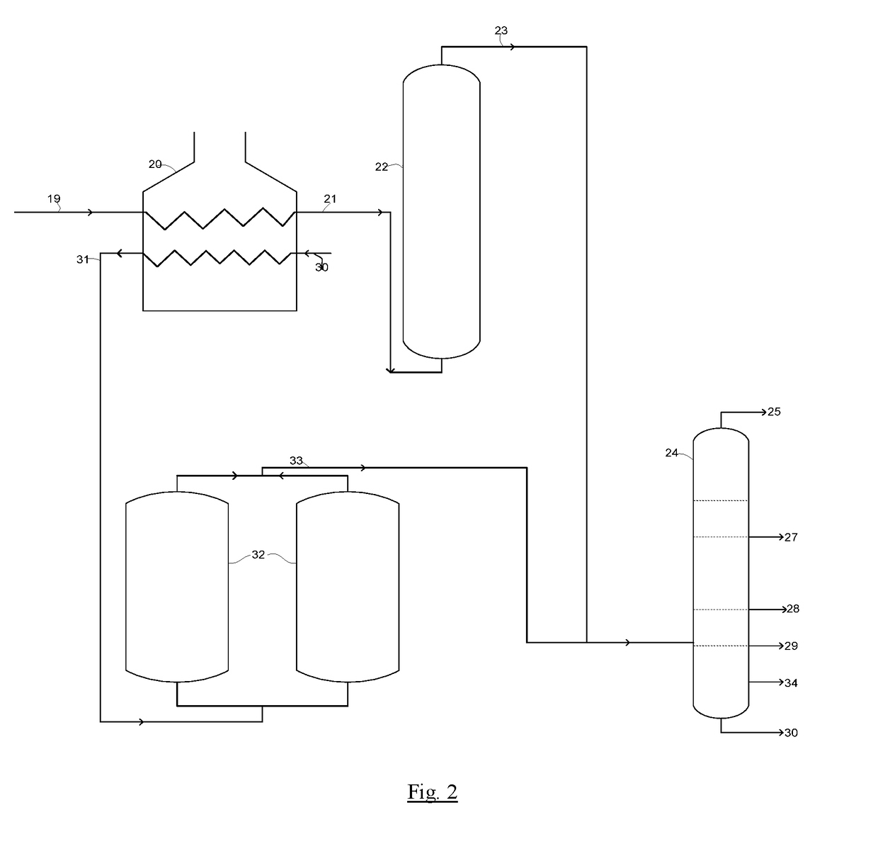
  • Delayed coking process with pre-cracking reactor
  • Delayed coking process with pre-cracking reactor
  • Delayed coking process with pre-cracking reactor

Examples


examples

[0094]Pilot scale experimental study is carried out for validating the merits of the invented process schemes. Experiments are carried out with a resid feedstock of characteristics provided in Table-1.

TABLE 1Properties of resid feedstockFeed characteristicsValueDensity, g / cc1.042CCR, wt %23.39Asphaltene content, wt %7.8Sulfur, wt %5.73Liquid analysis (D2887 / D6352) wt %Deg C. 040910506305625060070639806599068495698Metal, ppmFe6Na47Ca3Cr1Si1

[0095]A base case experiment is carried out in the delayed coker pilot plant using the resid feedstock at delayed coking conditions. The operating conditions for all the experiments are 495° C., feed furnace outlet line temperature, 14.935 psig coke drum pressure, 1 wt % steam addition to the coker feed and a feed rate maintained at about 8 kg / h. The operation is carried out in semi batch mode. The vapors from the coking drums are recovered as liquid and gas products and no coker product is recycled to the coker drum. Major operating parameters and...


PUM


Abstract

The present invention relates to delayed coking of heavy petroleum residue producing petroleum coke and lighter hydrocarbon products. The invented process utilize a pre-cracking reactor for mild thermal cracking of the feedstock and an intermediate separator, before being subjected to higher severity thermal cracking in delayed coking process, resulting in reduction in overall coke yield.

Description

FIELD OF THE INVENTION[0001]The present invention relates to the coking of heavy petroleum fractions or residues. More particularly, the present invention relates to conversion of heavy residue into lighter fractions in delayed coking process which resulting in improved overall yield of desired products and reduction in the yield of low value coke.BACKGROUND OF THE INVENTION[0002]Delayed cokers are furnace-type coking units wherein the feed is rapidly heated to temperatures above coking temperature inside a furnace and the effluent from the furnace discharges (before decomposition) into a large “coke drum”, where it remains until it either cracks or thermally decomposes and passes off as vapor and also condenses into coke.[0003]In the usual application of the delayed coking process, residual oil is heated by exchanging heat with liquid products from the coking process and is then fed into a fractionating tower where any light products which might remain in the residual oil are disti...

Claims


Application Information

Patent Timeline
IPC IPC(8): C10G55/04
CPCC10G55/04C10G2300/40C10G2300/107C10G2300/1077C10B55/00
Inventor KUMAR, BRIJESHDAS, SATYEN KUMARPRADEEP, PONOLY RAMACHANDRANPRASAD, TERAPALLI HARI VENKATA DEVIHARIPRASADGUPTA, BANDARU VENKATADIXIT, JAGDEV KUMARRAJESH,THAPA, GAUTAMBHATTACHARYYA, DEBASISDAS, BISWAPRIYA
Owner INDIAN OIL CORPORATION
Learn More