A waste heat recovery device

a waste heat recovery and waste heat technology, applied in steam engine plants, machines/engines, mechanical equipment, etc., can solve the problems of high fuel consumption and/or air resistance of the vehicle, low vehicle cooling efficiency, and limited cooling possibilities, so as to increase the cooling capacity of the vehicle. , the effect of cost-effectiv

Active Publication Date: 2017-06-01
VOLVO LASTVAGNAR AB
View PDF1 Cites 5 Cited by
  • Summary
  • Abstract
  • Description
  • Claims
  • Application Information

AI Technical Summary

Benefits of technology

[0013]By the provision of a waste heat recovery device, which comprises the first means for providing a first coolant from a first source and the further means for providing a further coolant from a further source, which sources are on different heat levels, the advantage that the thermodynamic engine may be provided with different cooling capability depending on the specific

Problems solved by technology

The cooling possibilities in a vehicle are however limited and in many applications already exhausted for cooling the internal combustion engine during high load ICE operation modes and in hot climates.
Even if it seems possible to increase the fan size and/or the fan power, this also results in higher fuel consumption and/or a higher air resistance of the vehicle.
However, when there is a high demand of power to the vehicle and possibly also a high ambient temperature, the cooling effic

Method used


Image

  • A waste heat recovery device
  • A waste heat recovery device
  • A waste heat recovery device

Examples


Embodiment Construction

[0042]In the following same or similar functional parts are indicated with the same reference numerals.

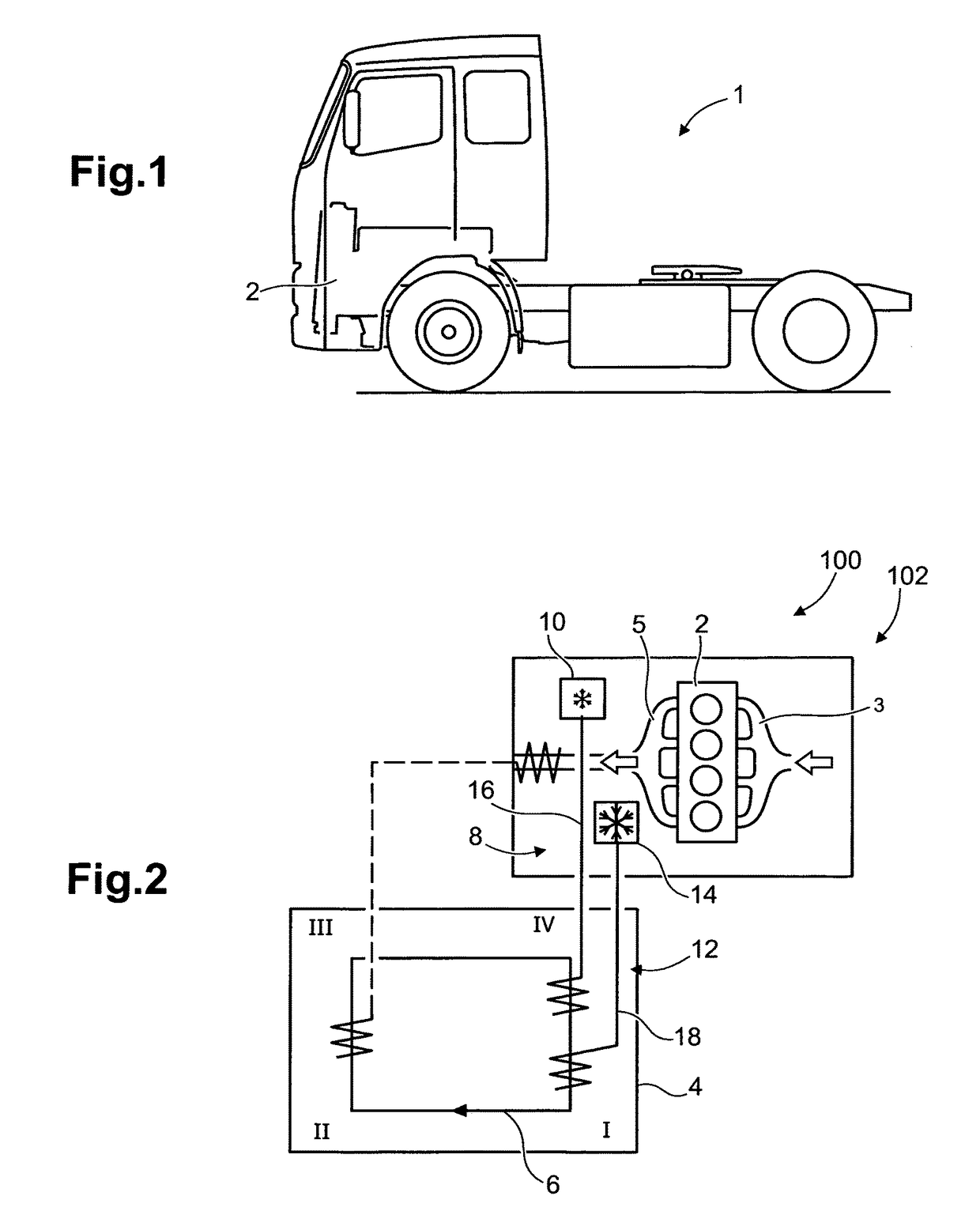
[0043]FIG. 1 shows a side view of a vehicle in the form of a truck 1. The truck 1 is provided with a source of motive power 2 for propelling the truck via a driveline connecting the power source to the wheels. The power source 2 is constituted by an internal combustion engine in the form of a diesel engine. It will in the following for ease of presentation be referred to as an internal combustion engine 2.

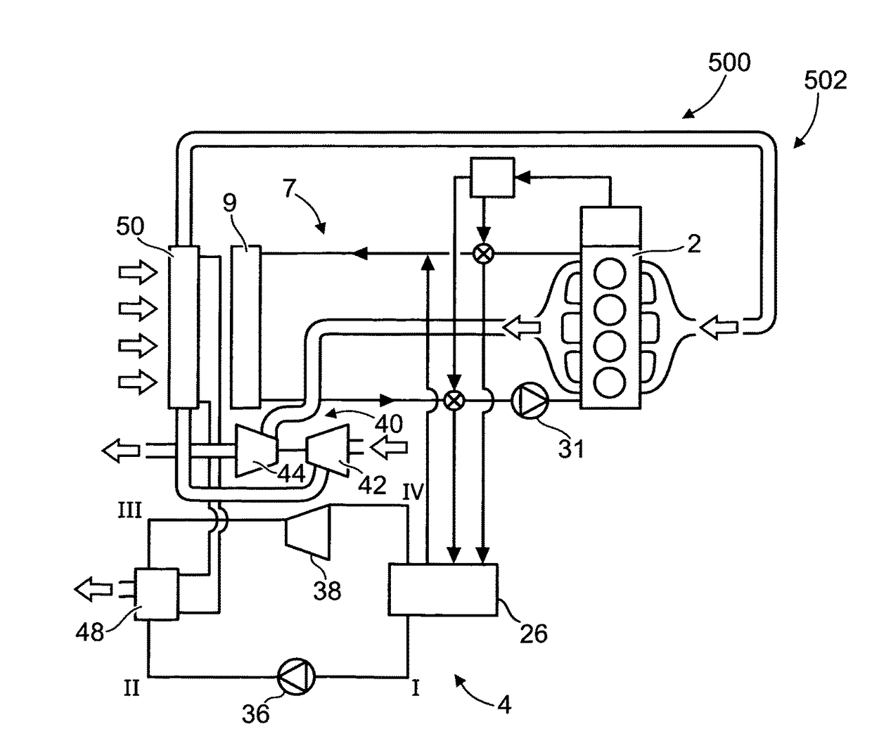
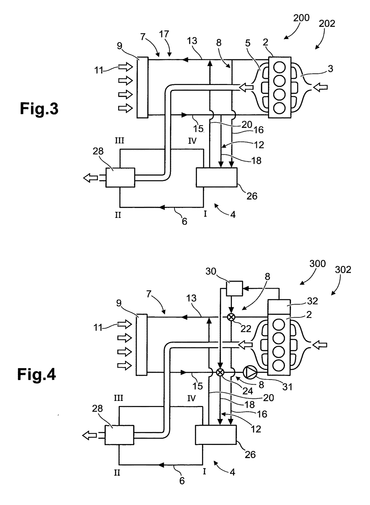
[0044]FIG. 2 shows an air intake side 3 and an exhaust side 5 of the internal combustion engine 1. FIG. 2 further shows a first embodiment example of a device 100 for recovery of waste heat generated during operation of the internal combustion engine 2. The waste heat recovery device 100 is arranged for recovery of waste heat from the exhaust gases of the internal combustion engine 1. The waste heat recovery device 100 comprises a thermodynamic engine 4, which comprises a working ...


PUM


Abstract

A device for recovery of waste heat generated during operation of an internal combustion engine includes a thermodynamic engine, which includes a working fluid circulation circuit and is configured for recovery of the waste heat a first arrangement for providing a first coolant from a first source for heat exchange with the working fluid in the working fluid circulation circuit, and at least one further arrangement for providing a further coolant from a further source for heat exchange with the working fluid in the working fluid circulation circuit, wherein the further source is at different heat level than the first source during operation of the internal combustion engine.

Description

BACKGROUND AND SUMMARY[0001]The invention relates to a device for recovery of waste heat generated during operation of an internal combustion engine and especially a diesel engine. The invention can be applied in vehicles and especially in heavy-duty vehicles such as trucks, buses and construction equipment (such as wheel loaders, excavators and articulated haulers). Although the invention will be described with respect to a truck, the invention is not restricted to this particular vehicle, but may also be used in other vehicles such as buses and construction equipment. The invention further relates to an engine system comprising the waste heat recovery device. The invention further relates to a vehicle comprising the engine system for recovery of waste heat of an internal combustion engine comprised in the vehicle. The invention further relates to a method for recovery of waste heat generated during operation of an internal combustion engine.[0002]The waste heat recovery device com...

Claims


Application Information

Patent Timeline
IPC IPC(8): F01K23/10F01K9/00F02B29/04F01N5/02
CPCF01K23/101F01N5/02F02B29/0475F02B29/0462F01K9/003F01K23/065Y02T10/12
Inventor ANDERSSON, LENNARTANDERSSON, ARNE
Owner VOLVO LASTVAGNAR AB
Why Eureka
Try Eureka