Directional atomizer system for cleaning chandeliers

Active Publication Date: 2017-06-08
INVENTIVE SOLUTIONS
View PDF5 Cites 6 Cited by
  • Summary
  • Abstract
  • Description
  • Claims
  • Application Information

AI Technical Summary

Benefits of technology

[0035]Another important object is to provide a chandelier cleaning apparat

Problems solved by technology

Conventional chandelier cleaning requires a labor-intensive, time-consuming dismantling of the chandelier and hand-washing of each part.
Floors and walls can still be marred by water as it splashes onto such tarps or drop cloths.
The water, which may contain dissolved chemicals, may also damage the floor simply by flowing off the tarp or drop cloths because such protective sheets have little or no water containment ability.
Complete saturation of the potting material by chemical sprays also weakens the bond and loosens such arms

Method used


Image

  • Directional atomizer system for cleaning chandeliers
  • Directional atomizer system for cleaning chandeliers
  • Directional atomizer system for cleaning chandeliers

Examples


Embodiment Construction

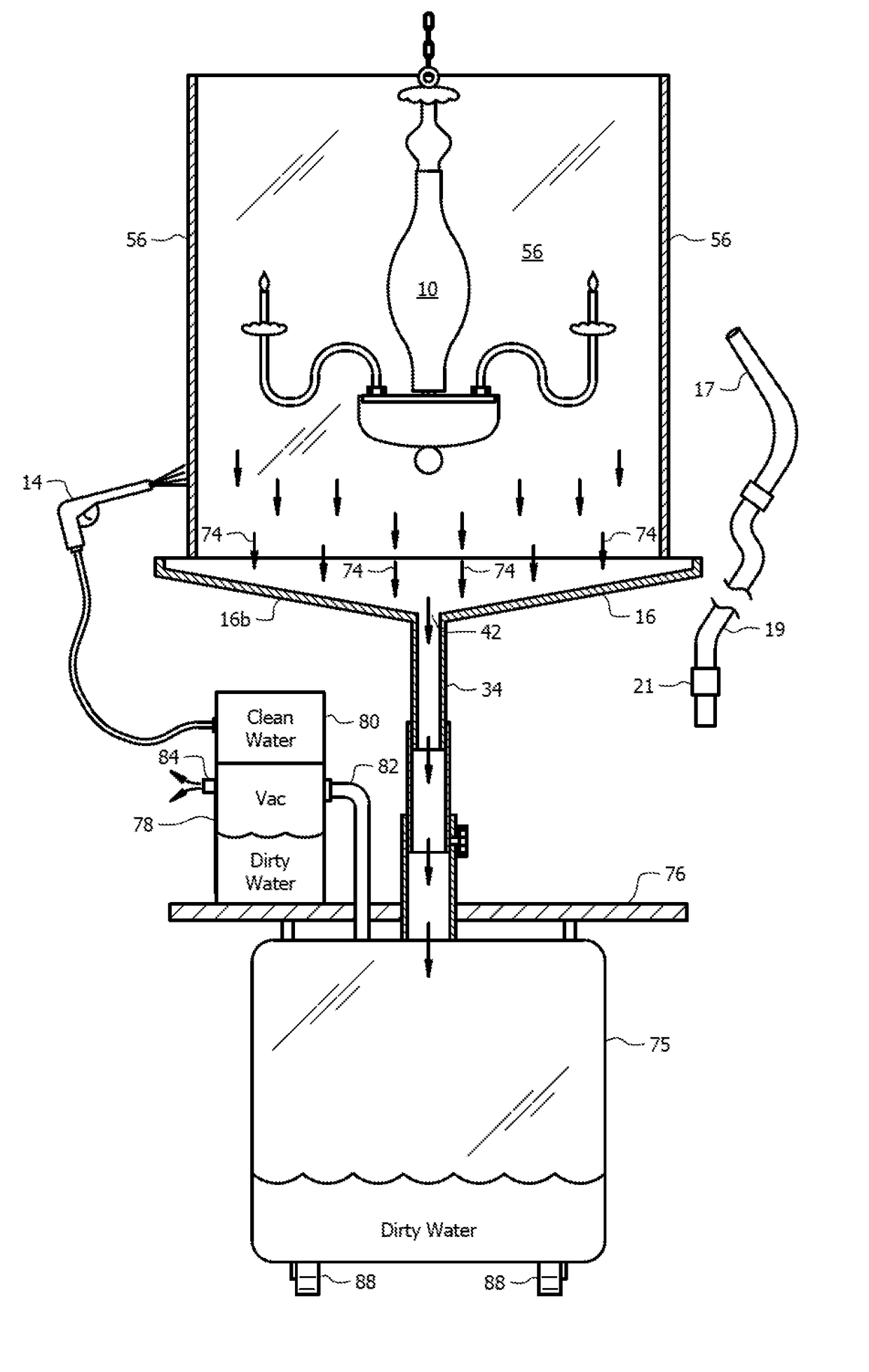
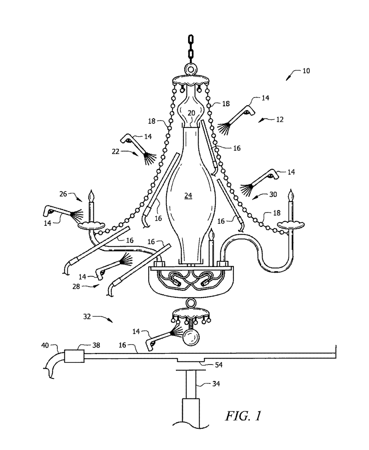
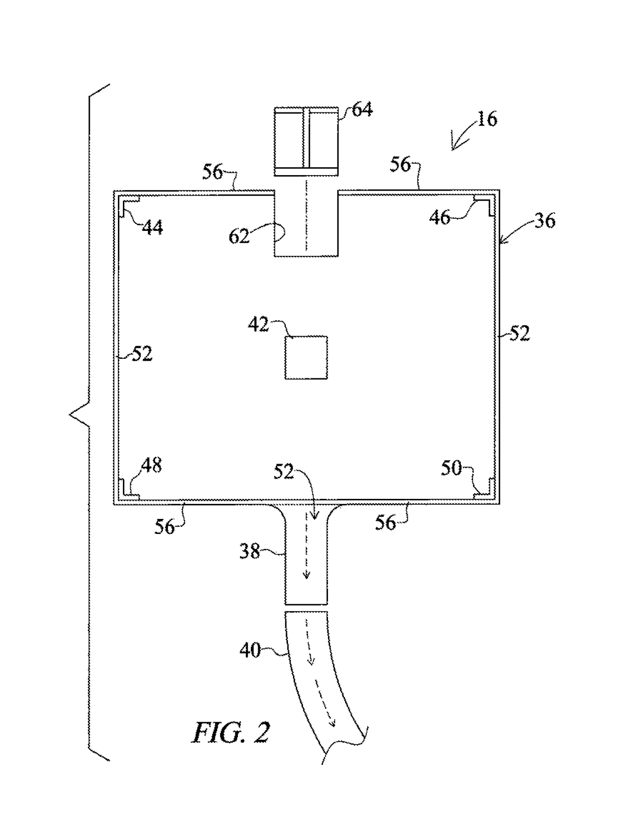
[0063]Referring now to the detailed figures, an embodiment of novel vacuum shield 16, as depicted in FIGS. 1-12, has hollow handle 38 the interior of which forms vacuum chamber 52 that is in fluid communication with a vacuum pump. As depicted in FIG. 3, an embodiment includes vacuum chamber 52 in fluid communication with five (5) vacuum inlets formed in vacuum shield 16, there being one vacuum inlet in each corner and one in the center of the vacuum shield 16. The vacuum pulls into said hollow interior small particles of water or mist to prevent such small particles from impinging against electrical wires, various electrical connections, check rings, sockets, potting that holds arms, and the like. The vacuum captures and removes mist from inside, around, and under an area occupied by a light fixture. Vacuum shield 16 also physically shields such parts from mist as well.

[0064]Novel vacuum shield 16 is preferably used with a variable pressure mist jet that controls deflection of hot m...


PUM


Abstract

An apparatus for cleaning chandeliers includes a hand-held fluid source having a proximal end connected to a source of hot water under positive pressure and a distal end having a spray head for discharging hot water under pressure in a spray pattern. A vacuum shield has at least one vacuum inlet connected to a source of negative pressure. Hot water discharged from the spray head is attracted to the vacuum shield when the spray head and the vacuum shield are disposed in relatively close proximity to one another and the vacuum shield is in fluid communication with the source of negative pressure. An object disposed between the spray head and the vacuum shield is cleansed by the action of hot water under positive pressure impinging against it. The vacuum shield protects objects not disposed between the spray head and the vacuum shield.

Description

CROSS-REFERENCE TO RELATED APPLICATIONS[0001]This nonprovisional application is a continuation-in-part of and claims priority to nonprovisional application Ser. No. 14 / 811,028, entitled “HAND-HELD TANK FOR CLEANING CHANDELIERS,” filed Jul. 28, 2015, which is a division of and claims priority to nonprovisional application Ser. No. 13 / 780,902, entitled “HAND-HELD TANK FOR CLEANING CHANDELIERS,” filed Feb. 28, 2013, issued on Aug. 25, 2015 as U.S. Pat. No. 9,114,442, which is a division of and claims priority to nonprovisional application Ser. No. 12 / 817,625, entitled “DIRECTIONAL ATOMIZER SYSTEM FOR CLEANING CHANDELIERS,” filed Jun. 17, 2010, issued on Mar. 26, 2013 as U.S. Pat. No. 8,402,596, all by the same inventor.BACKGROUND OF THE INVENTION[0002]1. Field of the Invention[0003]This invention relates, generally, to the art of cleaning chandeliers or other structurally complex lighting fixtures. More particularly, it relates to a system that cleans lighting fixtures without chemical...

Claims


Application Information

Patent Timeline
IPC IPC(8): B08B11/00A47L9/24A47L7/00B08B3/02
CPCB08B11/00A47L7/0004A47L9/242B08B3/026A47L7/00A47L7/0095A47L25/00B08B3/04B08B17/025
Inventor CAMPBELL, KEITH S.
Owner INVENTIVE SOLUTIONS
Why Eureka
Try Eureka