
Method of Natural Gas Liquefaction on LNG Carriers Storing Liquid Nitrogen

a technology of liquid nitrogen and natural gas, which is applied in the direction of passenger handling equipment, vessel auxilary devices, lighting and heating equipment, etc., can solve the problems of limited process train size, significant technical challenges in the application of the technology, and less appealing than the use of mixed refrigerant processes

Active Publication Date: 2017-06-15
EXXONMOBIL UPSTREAM RES CO
View PDF4 Cites 33 Cited by
  • Summary
  • Abstract
  • Description
  • Claims
  • Application Information

AI Technical Summary

Benefits of technology

The patent describes a new liquefaction process for producing liquefied natural gas (LNG) that has several advantages over current technologies. One advantage is that the power requirement for the process is much lower than conventional liquefaction processes, which means the liquefaction vessel can operate with less power. Another advantage is that the process can produce more LNG per vessel, meaning more natural gas can be liquefied. The liquefaction process also has the advantage of being fast startup and reduced thermal cycling, which lowers costs. The overall cost of the liquefaction module is expected to be significantly less than conventional modules. The disclosed technology could make it economical to have LNG carriers transport the gas to market, rather than transfer its cargo to less expensive shops. The patent outlines that the "technical effects" have numerous changes and alternatives, which can be made without limiting the scope of the patent.

Problems solved by technology

FLNG is a technology solution for monetizing offshore stranded gas where it is not economically viable to construct a gas pipeline to shore.
Although FLNG has several advantages over conventional onshore LNG, significant technical challenges remain in the application of the technology.
Although expander-based process has its advantages, the application of this technology to an FLNG project with LNG production of greater than 2 million tons per year (MTA) has proven to be less appealing than the use of the mixed refrigerant process.
The size of the expander-based process train is limited since its refrigerant mostly remains in the vapor state throughout the entire process and the refrigerant absorbs energy through its sensible heat.
Furthermore, the limitations in compander horsepower size results in parallel rotating machinery as the capacity of the expander-based process train increases.
However, the equipment count, complexity and cost all increase with multiple expander trains.
In open water, the design solutions for LNG transfer to merchant LNG ships becomes more limited and expensive.
In addition, the marine operations of tankers versus the FLNG facilities can become more complicated such as open-water berthing of a tanker either in tandem or side-by-side.
Design options become more limited and often more expensive as the designed-for ocean conditions become more severe.
Mandrin, however, has significant disadvantages that limit its application.
For example, since the liquefaction of the natural gas relies significantly on auto-refrigeration, the liquefaction process on the vessel has a poor thermodynamic efficiency when compared to known liquefaction processes that make use of one or more refrigerant streams.
Additionally, the need for a return gas pipeline significantly increases the complexity of fluid transfer between the floating structures.
The connection and disconnection of the two or more fluid pipelines between the FPU and the liquefaction vessel would be difficult if not impossible in open waters subject to waves and other severe metocean conditions.
While the disclosure of Prible et al. has an advantage of using a liquefaction process that is significantly more efficient than the disclosure of Mandrin, using multiple gas pipeline connections between the floaters limits the application of this technology in challenging metocean conditions.
The FLNG technology solution described in U.S. Pat. No. 8,646,289 also has several challenges and limitations that may limit its application.
For example, the liquefaction vessel is likely to be much more costly than a conventional LNG carrier because of the significant increase in onboard power demand and the change in the propulsion system.
This option, however, is only expected to marginally reduce cost since electric propulsion for LNG carriers is not widely used in the industry.
Furthermore, the required amount of installed power is still three to four more times greater than what would be required for propulsion of a conventional LNG carrier.
Another limitation of the FLNG technology solution described in U.S. Pat. No. 8,646,289 is that the dual nitrogen expansion process limits the production capacity of each liquefaction vessel to approximately 2 MTA or less.
Still another limitation of the FLNG technology solution described in U.S. Pat. No. 8,646,289 is that the technology has the disadvantage of requiring frequent startup, shutdown and turndown of the liquefaction system of the liquefaction vessel.
However, the required frequency of startup and shutdown is still significantly greater than previous experience with the dual nitrogen expansion technology at the production capacities of interest.
Thermal cycling of process equipment as well as other issues associated with frequent startups and shutdowns are considered new and significant risks to the application of this technology.
Yet another limitation of the FLNG technology solution described in U.S. Pat. No. 8,646,289 is that the required power plant and liquefaction trains for this technology are expected to significantly increase the capital and operational cost of the liquefaction vessel over the typical cost of a conventional LNG carrier.
This technology limits the 
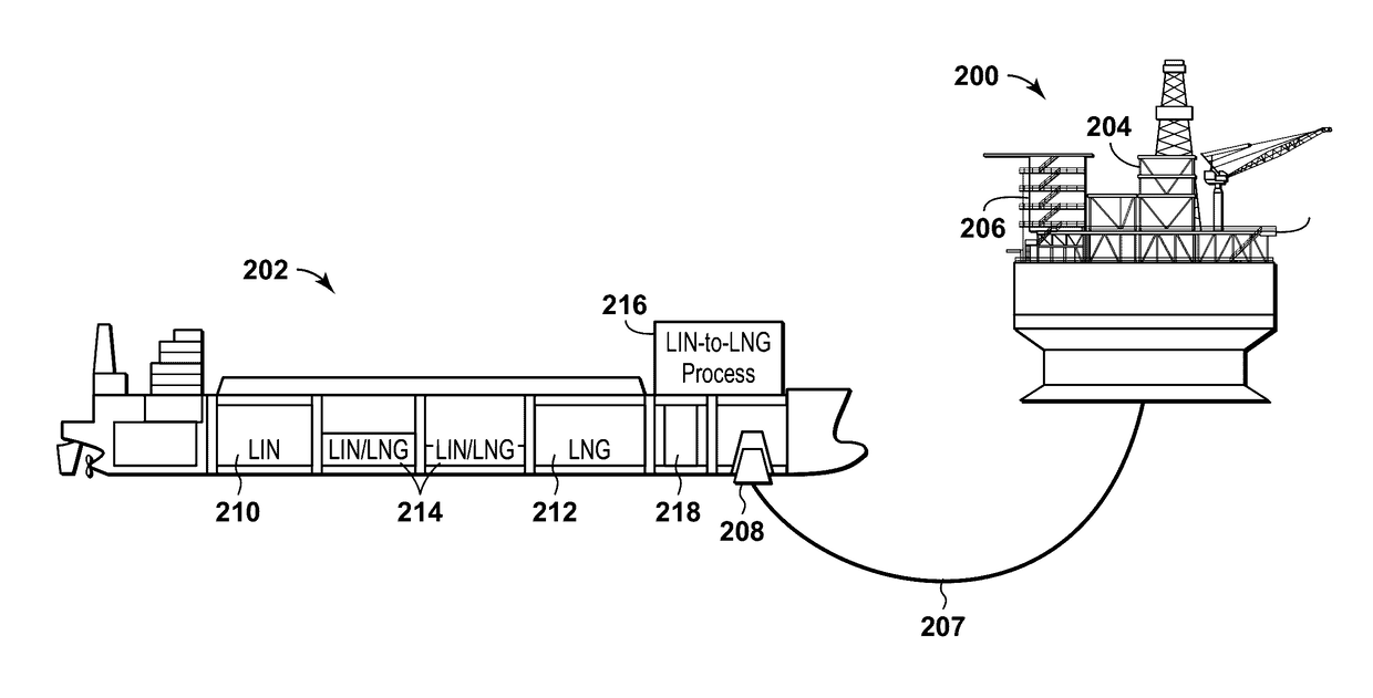
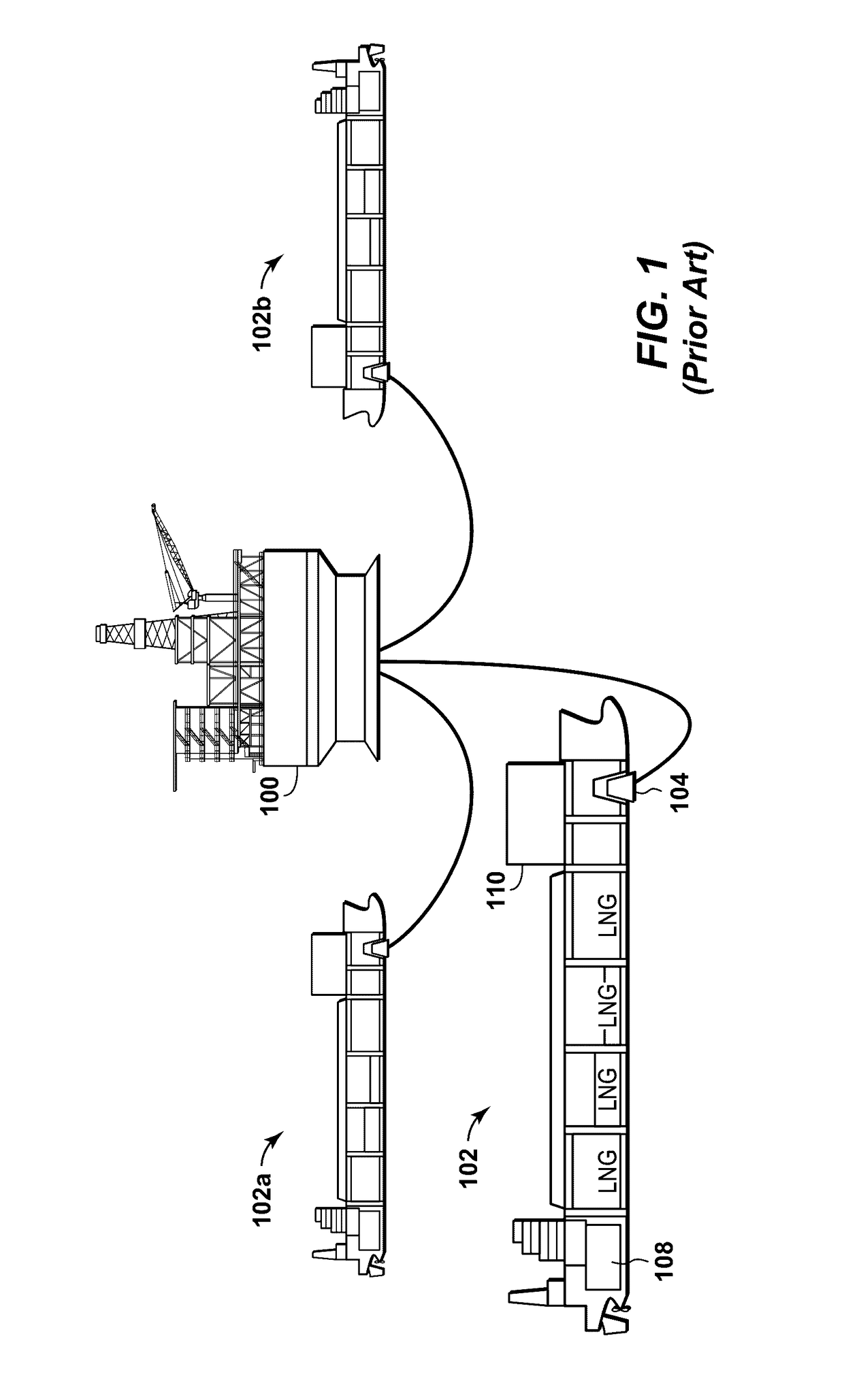
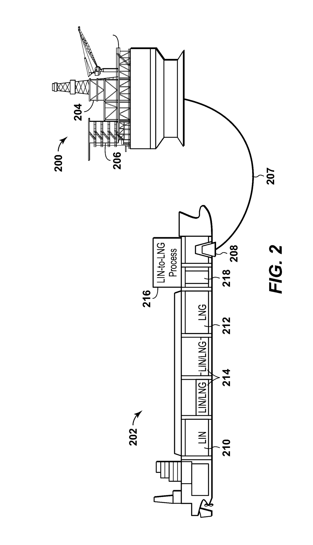
impact of the high cost of the liquefaction vessel, by proposing an LNG value chain where the loaded LNG liquefaction vessel moves to an intermediate transfer terminal where it offloads the LNG on to conventional LNG carriers.

Method used


Image

  • Method of Natural Gas Liquefaction on LNG Carriers Storing Liquid Nitrogen
  • Method of Natural Gas Liquefaction on LNG Carriers Storing Liquid Nitrogen
  • Method of Natural Gas Liquefaction on LNG Carriers Storing Liquid Nitrogen

Examples


Embodiment Construction

[0035]To promote an understanding of the principles of the disclosure, reference will now be made to the features illustrated in the drawings and specific language will be used to describe the same. It will nevertheless be understood that no limitation of the scope of the disclosure is thereby intended. Any alterations and further modifications, and any further applications of the principles of the disclosure as described herein are contemplated as would normally occur to one skilled in the art to which the disclosure relates. For the sake clarity, some features not relevant to the present disclosure may not be shown in the drawings.

[0036]At the outset, for ease of reference, certain terms used in this application and their meanings as used in this context are set forth. To the extent a term used herein is not defined below, it should be given the broadest definition persons in the pertinent art have given that term as reflected in at least one printed publication or issued patent. ...


PUM


Abstract

A method for producing liquefied natural gas (LNG). A natural gas stream is transported to a liquefaction vessel. The natural gas stream is liquefied on the liquefaction vessel using at least one heat exchanger that exchanges heat between the natural gas stream and a liquid nitrogen stream to at least partially vaporize the liquefied nitrogen stream, thereby forming a warmed nitrogen gas stream and an at least partially condensed natural gas stream comprising LNG. The liquefaction vessel includes at least one tank that only stores liquid nitrogen and at least one tank that only stores LNG.

Description

CROSS REFERENCE TO RELATED APPLICATIONS[0001]This application claims the benefit of U.S. Provisional Patent Application 62 / 266,983, filed Dec. 14, 2015 entitled METHOD OF NATURAL GAS LIQUEFACTION ON LNG CARRIERS STORING LIQUID NITROGEN, the entirety of which is incorporated by reference herein.[0002]This application is related to U.S. Provisional Patent Application No. 62 / 266,976 titled “Method and System for Separating Nitrogen from Liquefied Natural Gas Using Liquefied Nitrogen;” U.S. Provisional Patent Application No. 62 / 266,979 titled “Expander-Based LNG Production Processes Enhanced With Liquid Nitrogen;” and U.S. Provisional Patent Application No. 62 / 622,985 titled “Pre-Cooling of Natural Gas by High Pressure Compression and Expansion,” all having common inventors and assignee and filed on an even date herewith, the disclosure of which is incorporated by reference herein in their entirety.BACKGROUND[0003]Field of Disclosure[0004]The disclosure relates generally to the field of...

Claims


Application Information

Patent Timeline
IPC IPC(8): F25J1/02F25J1/00
CPCF25J1/0277F25J1/0022F25J1/0072F25J1/0221F25J2210/60F25J2290/60F25J2240/02F25J2240/12F25J2235/42F25J2290/72F25J2270/16F25J1/0015F25J1/0042F25J1/005F25J1/0204F25J1/0223F25J1/0265F25J1/0278F25J2210/42F25J2210/62F25J2230/20B63B21/507B63B25/16B63B27/34B63J3/04F17C6/00F17C2227/0341F17C2270/0105
Inventor PIERRE, JR., FRITZVICTORY, DONALD J.
Owner EXXONMOBIL UPSTREAM RES CO
Learn More