

Temperature-triggered viscosifier for treatment of a subterranean formation
- Summary
- Abstract
- Description
- Claims
- Application Information
AI Technical Summary
Benefits of technology
Problems solved by technology
Method used
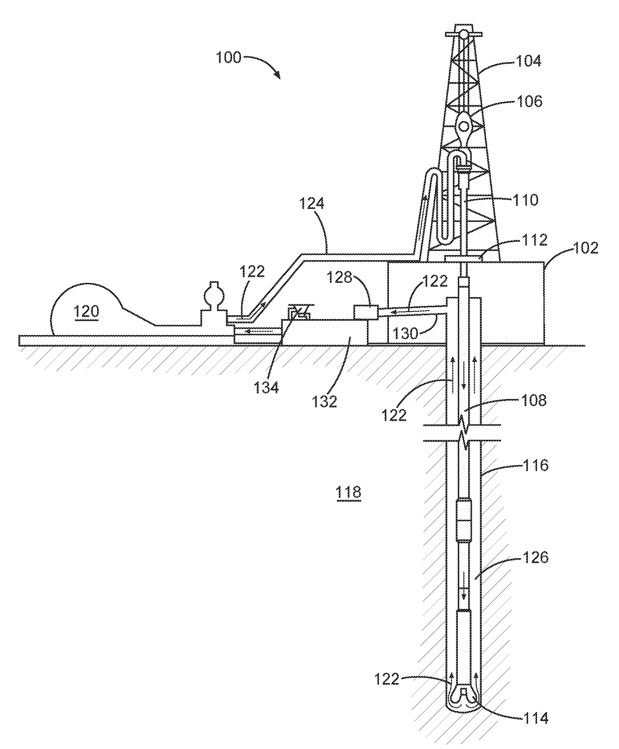
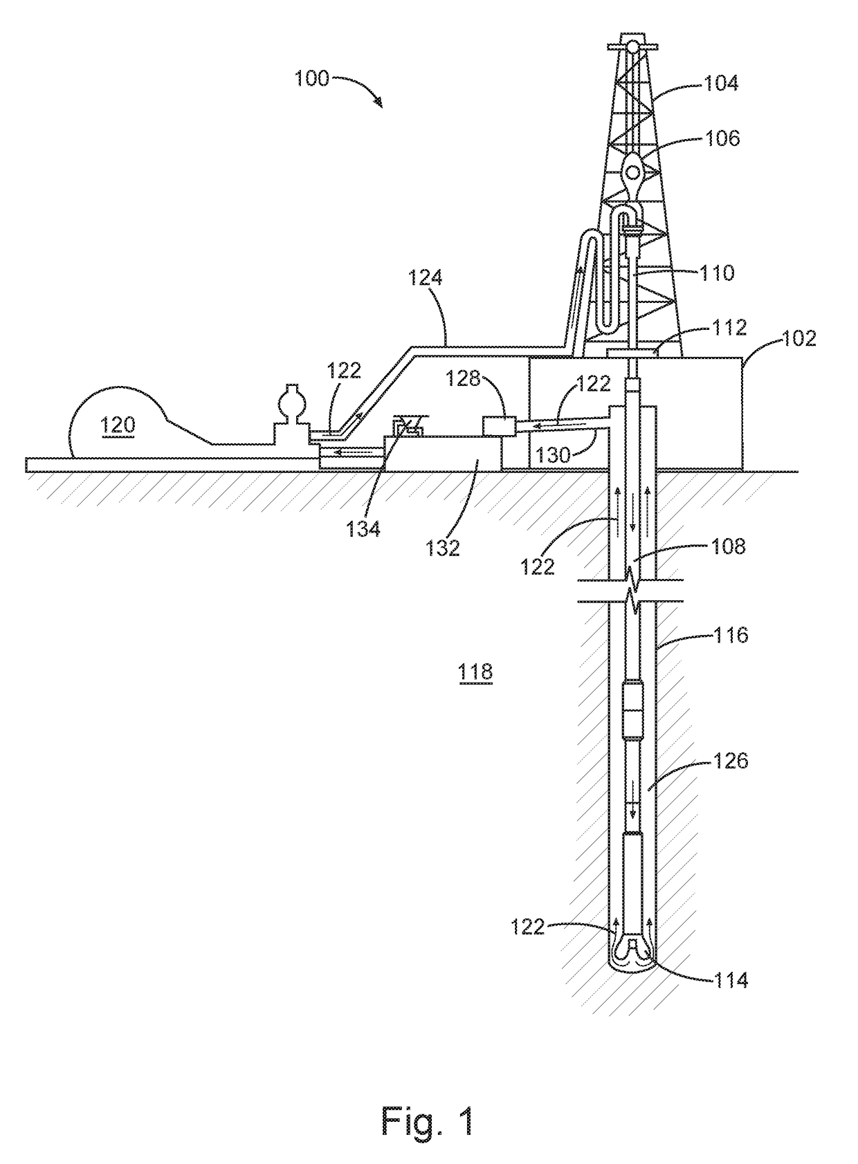
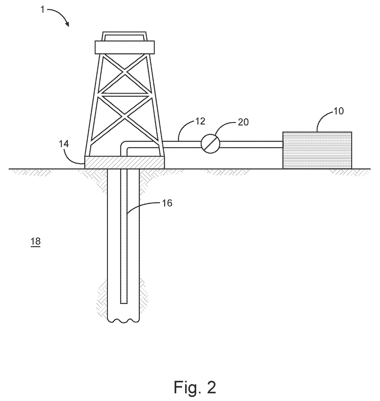
Image

Examples
example 1
lymer Solution Preparation and Heat Treatment
[0135]Two sample polymer solutions were prepared by dissolving 0.7 ppb (pounds per barrel) of an acrylamide copolymer (having 40 mol % acrylamide-drived monomers, 40 mol % acrylamidopropanesulfonic acid-derived monomers, and about 10 mol % acrylic acid-derived monomers, with an average molecular weight of about 7-10 million daltons) and 0.175 ppb of a zirconium-derivative crosslinker (0.175 ppb cross-linker) in water. The sample polymer solutions were aged in an oven at 200° F. or 225° F. for 16 hours.
example 2
Measurements of Heat-Treated Sample Polymer Solutions
[0136]Viscosity of the heat-treated polymer samples were measured by an advanced Rheometer (Anton Paar) at 200° F. using a shear rate of 100 s−1 and at standard pressure, with the results shown in FIG. 3.
[0137]As compared to the viscosity provided by the polymer sample receiving a temperature treatment at 200° F., the polymer sample with the 225° F. temperature treatment provided a viscosity that was about 30% greater due to increased crosslinking caused by the higher temperatures.
[0138]The terms and expressions that have been employed are used as terms of description and not of limitation, and there is no intention in the use of such terms and expressions of excluding any equivalents of the features shown and described or portions thereof, but it is recognized that various modifications are possible within the scope of the embodiments of the present invention. Thus, it should be understood that although the present invention has ...
PUM
| Property | Measurement | Unit |
|---|---|---|
| Molar mass | aaaaa | aaaaa |
| Molar mass | aaaaa | aaaaa |
| Molecular weight | aaaaa | aaaaa |
Abstract
Description
Claims
Application Information