Unlock instant, AI-driven research and patent intelligence for your innovation.

Optical distance measuring apparatus

a technology of optical distance measurement and measuring apparatus, which is applied in the direction of instruments, measurement devices, microscopes, etc., can solve the problems of damage, difficult three-dimensional measurement, and inability to observe or measure objects,

Active Publication Date: 2017-06-22
ASTRODESIGN
View PDF2 Cites 8 Cited by
  • Summary
  • Abstract
  • Description
  • Claims
  • Application Information

AI Technical Summary

Benefits of technology

The present invention relates to an optical distance measuring apparatus that can achieve high resolution measurement of the surface state of an object under measurement, including the ability to observe and measure in real-time three-dimensional information regarding a biological sample with a thickness such as a cell, in a living state, without damaging the sample. The invention uses an optical heterodyne interference method to measure the distance and thickness of an object under measurement by detecting the phase change of a beat signal. The technical effect of the invention is to increase the resolution and accuracy of optical distance measurement and observation of biological samples.

Problems solved by technology

With a conventional optical microscope, it has been difficult to perform three-dimensional measurement, and besides, it has not been possible to observe or measure an object under measurement at or below a diffraction limit.
Accordingly, this often accompanies damage to a cell itself, and of course it has not been possible to observe or measure a live cell.
However, it is difficult to move the probe at high speed, handling is difficult because the distance to the object under measurement is quite close, and moreover a long time is needed for obtaining two-dimensional information.
However, in the confocal microscope, basically, when there is a phase distribution within a spot, the beam is deformed, which results in erroneous information.
In particular, for an object under measurement on which a wavefront changes in phase, like a refractive index change in a cell or the like, it must be said that reliability of the value thereof is poor.
Further, it is necessary to move the objective lens or the object under measurement so that the received amount of light becomes maximum, and thus the measurement cannot be performed in real time.
Therefore, according to this Patent Document 1, it is possible to measure concave and convex information of an object under measurement which is assumed to be flat such as a semiconductor wafer, but it is not possible to extract information inside the beam profile.
Accordingly, it is not possible to increase the resolution inside the beam profile, which is in a plane.
From the foregoing, with the conventional technique of the microscope and the like, it has not been possible not only to increase the resolution inside the beam profile, which is in a plane, but also to observe or measure, in real time, three-dimensional information regarding a biological sample having a thickness such as a cell, in a living state, without damaging the sample.
Note that the reason why the photo detector is positioned by being displaced to any one side with respect to the boundary line, is because when the photo detector is positioned at a center of the optical axis, phases are reversed across the boundary line, which makes it difficult to obtain sufficient data from the irradiation light.

Method used


Image

  • Optical distance measuring apparatus
  • Optical distance measuring apparatus
  • Optical distance measuring apparatus

Examples


embodiment 1

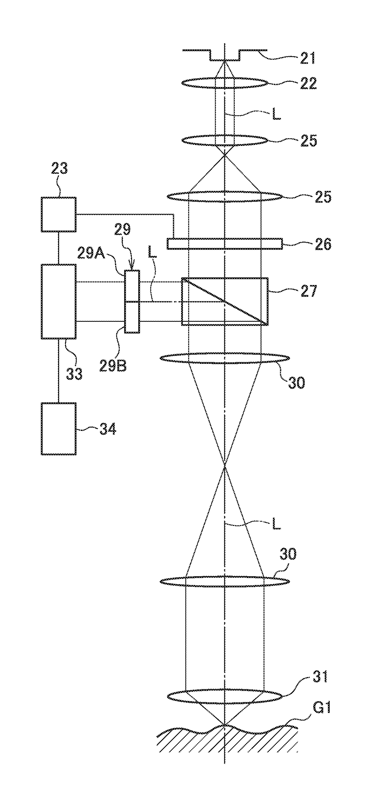
[0064]Embodiment 1 of the optical distance measuring apparatus according to the present invention will be described hereinafter while referring to FIG. 1 and FIG. 2. The present embodiment employs an apparatus of a reflective optical system which reflects a scanning beam by an object under measurement. FIG. 1 is a block diagram illustrating a configuration of the apparatus of the reflective optical system according to the embodiment.

[0065]As illustrated in FIG. 1, a laser light source 21 being a light source from which a laser light being a coherent irradiation light is irradiated (emitted), and a collimator lens 22 on which aberration correction is performed so that a collimated light can be obtained from the laser light, are disposed in sequence. Therefore, in the present embodiment, the laser light emitted from the laser light source 21 is turned into the collimated light by the collimator lens 22.

[0066]Further, a pupil transmission lens system 25 formed of two groups of lenses, ...

embodiment 2

[0083]Next, Embodiment 2 of the optical distance measuring apparatus according to the present invention will be described hereinafter while referring to FIG. 4. The present embodiment employs an apparatus of a transmitted optical system in which a scanning beam transmits through an object under measurement.

[0084]FIG. 4 is a block diagram illustrating the apparatus of the transmitted optical system according to the present embodiment. The major part of the optical system is the same as the apparatus of the reflective optical system described above, and thus is omitted from description. In the apparatus of the transmitted optical system, when compared with Embodiment 1, the lights gathered at the objective lens 31 transmit through an object under measurement G2.

[0085]Further, in the present embodiment, since the transmitted optical system is employed, the beam splitter 27 is not necessary, and in accordance with this, the photo detector group 29 is disposed at a position on the opposi...

embodiment 3

[0124]Next, Embodiment 3 of the optical distance measuring apparatus according to the present invention will be described hereinafter while referring to FIG. 7. The present embodiment can be applied to an apparatus of a reflective optical system and an apparatus of a transmitted optical system.

[0125]In Embodiments 1, 2, the photo detectors 29A, 29B forming the photo detector group 29 are respectively positioned in the two divided regions with the boundary line S interposed therebetween, the boundary line S being positioned on the surface which is substantially perpendicular to the direction along the optical axis L of the scanning beam LA, and passing in through the optical axis L. On the contrary, the present embodiment employs four divided photo detectors 29A to 29D illustrated in FIG. 7, so that they can obtain respective pieces of information in a horizontal direction and a perpendicular direction within a plane of the object under measurement G1, G2.

[0126]Specifically, it is se...


PUM


Abstract

An optical distance measuring apparatus includes: a scanning element scanning a coherent irradiation light from a light source and sending it to an object under measurement; a photo detector receiving the irradiation light modulated by being passed through the object under measurement in accordance with the scanning, and performing photoelectric conversion on the irradiation light; and a measuring unit obtaining phase information of the object under measurement based on a signal photoelectrically converted by the photo detector and a signal to be a reference for the scanning by the scanning element, and obtaining a measurement value regarding the object under measurement based on the phase information.

Description

BACKGROUND OF THE INVENTION[0001]1. Field of the Invention[0002]The present invention relates to an optical distance measuring apparatus realizing, with a quite high resolution, measurement of a profile of a surface state of an object under measurement, measurement or observation of a surface state and an internal state of a cell or the like by irradiation of laser lights, and is preferable for an apparatus improving a resolution of an optical apparatus such as a microscope.[0003]2. Description of the Related Art[0004]With a conventional optical microscope, it has been difficult to perform three-dimensional measurement, and besides, it has not been possible to observe or measure an object under measurement at or below a diffraction limit. As a substitute for this, apparatuses such as a scanning electron microscope, a probe microscope (STM, AFM, NFOS, or the like), and a confocal microscope have been developed and used in many fields.[0005]The scanning electron microscope uses a very...

Claims


Application Information

Patent Timeline
IPC IPC(8): G01B11/24G02B21/00G01B11/245
CPCG01B11/24G02B21/0096G01B11/245G01B9/02097G01B9/04G02B21/0056
Inventor TAKESUE, TOSHIHARUTAKEDA, SHIGETONISHIZAWA, NOBUYUKIARIMA, TATSUHOSUZUKI, SHIGEAKI
Owner ASTRODESIGN
Features
  • R&D
  • Intellectual Property
  • Life Sciences
  • Materials
  • Tech Scout
  • Unparalleled Data Quality
  • Higher Quality Content
  • 60% Fewer Hallucinations
Learn More