Developing roller, and method of producing the same

Active Publication Date: 2017-06-22
SUMITOMO RUBBER IND LTD
View PDF4 Cites 0 Cited by
  • Summary
  • Abstract
  • Description
  • Claims
  • Application Information

AI Technical Summary

Benefits of technology

The invention provides a developing roller with a flexible inner layer and an outer layer of a tube that is excellent at sliding and resistant to wear. This roller is designed to prevent the toner from becoming damaged, and a method for producing it is also provided.

Problems solved by technology

Therefore, parts of the outer peripheral surface of the developing roller against which opposite edge portions of the layer forming blade are kept in abutment are problematically liable to be worn or damaged in a short period of time, and the toner is often liable to leak laterally from the opposite edge portions of the layer forming blade.
Particularly, where the developing roller is allowed to have a porous structure to be imparted with an improved flexibility by foaming and crosslinking the semiconductive rubber composition with the use of a foaming agent, the problem of the lateral toner leakage tends to occur in a shorter period of time.
However, the coating layer of the urethane resin or the phenol resin has a poorer slidability though being excellent in wear resistance.
Therefore, the developing roller is liable to have an increased rotation torque, making it difficult to properly perform the image formation.
On the other hand, the coating layer of the fluororesin or the silicone resin is excellent in slidability but has an insufficient wear resistance and, therefore, is liable to be worn to lose its effect in a shorter period of time.
The use of the organic solvent may exert a great load on the environment, and go against a recent trend toward reduction of VOC (volatile organic compounds).

Method used


Image

  • Developing roller, and method of producing the same
  • Developing roller, and method of producing the same
  • Developing roller, and method of producing the same

Examples


example 1

[0140]Of ethylene propylene rubbers, an EPDM (ESPRENE EPDM 505A available from Sumitomo Chemical Co., Ltd. and having a Mooney viscosity ML1+4 (100° C.) of 47, an ethylene content of 50% and a diene content of 9.5%) was used as a rubber component.

[0141]DIANA PROCESS OIL PW-380 available from Idemitsu kosan Co., Ltd. was used as a paraffin oil.

[0142]While 100 parts by mass of the EPDM was simply kneaded by means of a Banbury mixer, 60 parts by mass of the paraffin oil and ingredients other than a crosslinking component and a foaming component shown below in Table 1 were added to and kneaded with the EPDM, and then the crosslinking component and the foaming component were added to and further kneaded with the resulting mixture. Thus, a semiconductive rubber composition for an inner layer was prepared.

TABLE 1IngredientsParts by massFiller30Crosslinking assisting agent (I)5Crosslinking assisting agent (II)1Electron conductive agent50Foaming agent6Foaming assisting agent2Crosslinking age...

example 2

[0156]A developing roller was produced in substantially the same manner as in Example 1, except that the proportion of the ADCA blended as the foaming agent in the semiconductive rubber composition was 5 parts by mass.

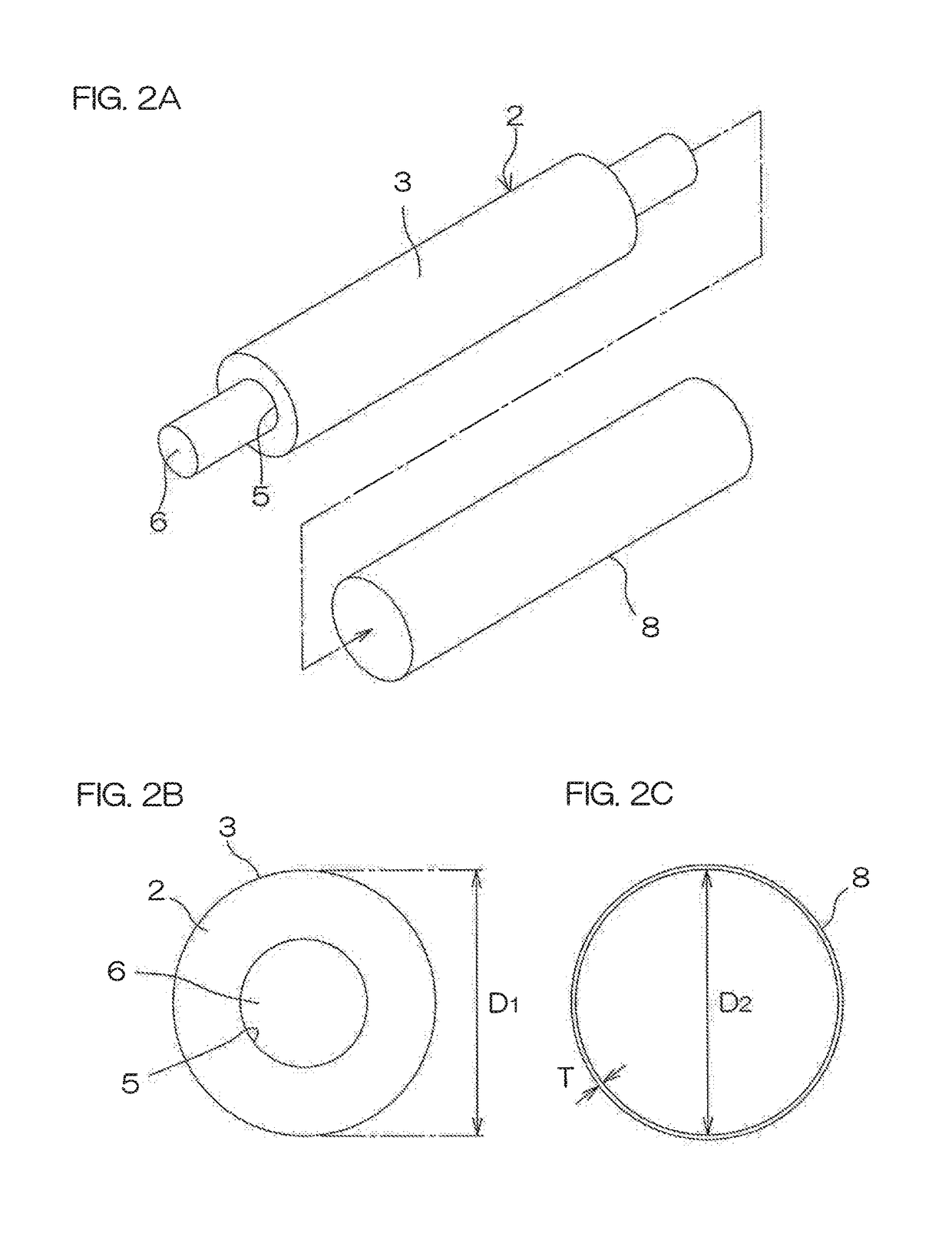
[0157]The tube for the outer layer had a wall thickness T of 100 μm, and an interference represented by a difference D1-D2 between the outer diameter D1 and the inner diameter D2 was 200 μm.

[0158]The developing roller had an overall Asker-C hardness of 45 degrees. The outer peripheral surface of the developing roller had a profile curve arithmetic average roughness Ra of 1 μm.

example 3

[0159]A developing roller was produced in substantially the same manner as in Example 1, except that the outer diameter D1 of the inner layer was 15.80 mm, and a seamless semiconductive thermoplastic polyamide elastomer tube SLV (available from Gunze Limited) having an inner diameter D2 of 15.60 mm and a wall thickness T of 200 μm was used for the outer layer.

[0160]As described above, the wall thickness T of the tube for the outer layer was 200 μm, and an interference represented by a difference D1-D2 between the outer diameter D1 and the inner diameter D2 was 200 μm.

[0161]The developing roller had an overall Asker-C hardness of 47 degrees. The outer peripheral surface of the developing roller had a profile curve arithmetic average roughness Ra of 1 μm.


PUM

PropertyMeasurementUnit
Lengthaaaaaaaaaa
Lengthaaaaaaaaaa
Lengthaaaaaaaaaa

Abstract

A developing roller (1) is provided, which includes a tubular porous inner layer (2) of a foamed product of a semiconductive rubber composition containing an ethylene propylene rubber and a paraffin oil, and an outer layer (4) of a seamless tube of a semiconductive thermoplastic polyamide elastomer provided on an outer peripheral surface (3) of the inner layer (2), and has an overall Asker-C hardness of not less than 30 degrees and not greater than 60 degrees. A production method is also provided, which includes the steps of: preparing a tube having a thickness T of 100 to 400 μm and having an inner diameter D2 for an outer layer; preparing a tubular inner layer having an outer diameter D1; and press-inserting the inner layer into the tube; wherein an interference represented by a difference D1−D2 between the outer diameter D1 of the inner layer and the inner diameter D2 of the tube is 100 to 400 μm.

Description

TECHNICAL FIELD[0001]The present invention relates to a developing roller to be incorporated in an electrophotographic image forming apparatus, and to a method of producing the developing roller.BACKGROUND ART[0002]In an electrophotographic image forming apparatus such as a laser printer, an electrostatic copying machine, a plain paper facsimile machine or a printer-copier-facsimile multifunction machine, a developing roller is used for developing an electrostatic latent image formed on a surface of a photoreceptor body into a toner image[0003]In general, the developing roller is produced by blending an electron conductive agent and / or an ion conductive agent with a rubber to prepare a semiconductive rubber composition imparted with a semiconductivity, forming the semiconductive rubber composition into a tubular body, and crosslinking the tubular body.[0004]In recent years, the developing roller is required to have a reduced diameter for size reduction of the image forming apparatus...

Claims


Application Information

Patent Timeline
IPC IPC(8): G03G15/08
CPCG03G15/0808B32B1/00B32B25/042C08J9/103C08L23/16B32B2307/746B32B2307/554B32B2250/248B32B2307/202C08J2323/16C08J2203/04C08K2003/265C08K2003/2296C08J2491/06C08L2203/14C08L91/06C08K13/02C08K3/04C08K3/26C08K3/06C08K3/22C08K5/09G03G15/0818
Inventor IMASE, YUTA
Owner SUMITOMO RUBBER IND LTD
Why Eureka
Try Eureka