
EUV lpp source with improved dose control by tracking dose over specified window

a technology of euv radiation and dose control, which is applied in the direction of x-ray tubes, electric discharge tubes, x-ray apparatuses, etc., can solve the problems of incomplete extraction of power amplifier gain, further variations in euv pulse energy, and less stable plasma, so as to improve the control of a dose of euv radiation

Active Publication Date: 2017-06-22
ASML NETHERLANDS BV
View PDF0 Cites 7 Cited by
  • Summary
  • Abstract
  • Description
  • Claims
  • Application Information

AI Technical Summary

Benefits of technology

The patent describes a method and device for controlling the amount of ultraviolet (EUV) light that is applied to a semiconductor wafer during processing. The invention helps to improve the accuracy and precision of the dosage, which can enhance the overall quality and efficiency of the manufacturing process.

Problems solved by technology

One issue is that it is desirable, and in fact important, to be able to control the amount, or “dose,” of EUV light energy being applied to a particular item being treated, such as a semiconductor wafer.
This is complicated by the fact that the power in each laser pulse may vary.
The problem with packet-based dose control is that due to the variation in laser pulse energy, and thus in the EUV energy generated by each droplet, different packets may end up with very different numbers of pulses that actually generate energy.
This variation in temperature can lead to a less stable plasma and in turn cause further variations in the EUV pulse energy.
The problem with the EUV stabilization approach is that reduction of the master oscillator pulse energy leads to incomplete extraction of the gain in the power amplifier.
As is well known in the art, this can lead to self-lasing and large amounts of reflected power from the droplets that can damage optical components in the system.
Additionally, reducing the laser energy hitting the droplet can produce increased amount of debris due to incomplete evaporation of the target, which is not desirable in the source.

Method used


Image

  • EUV lpp source with improved dose control by tracking dose over specified window
  • EUV lpp source with improved dose control by tracking dose over specified window
  • EUV lpp source with improved dose control by tracking dose over specified window

Examples


Embodiment Construction

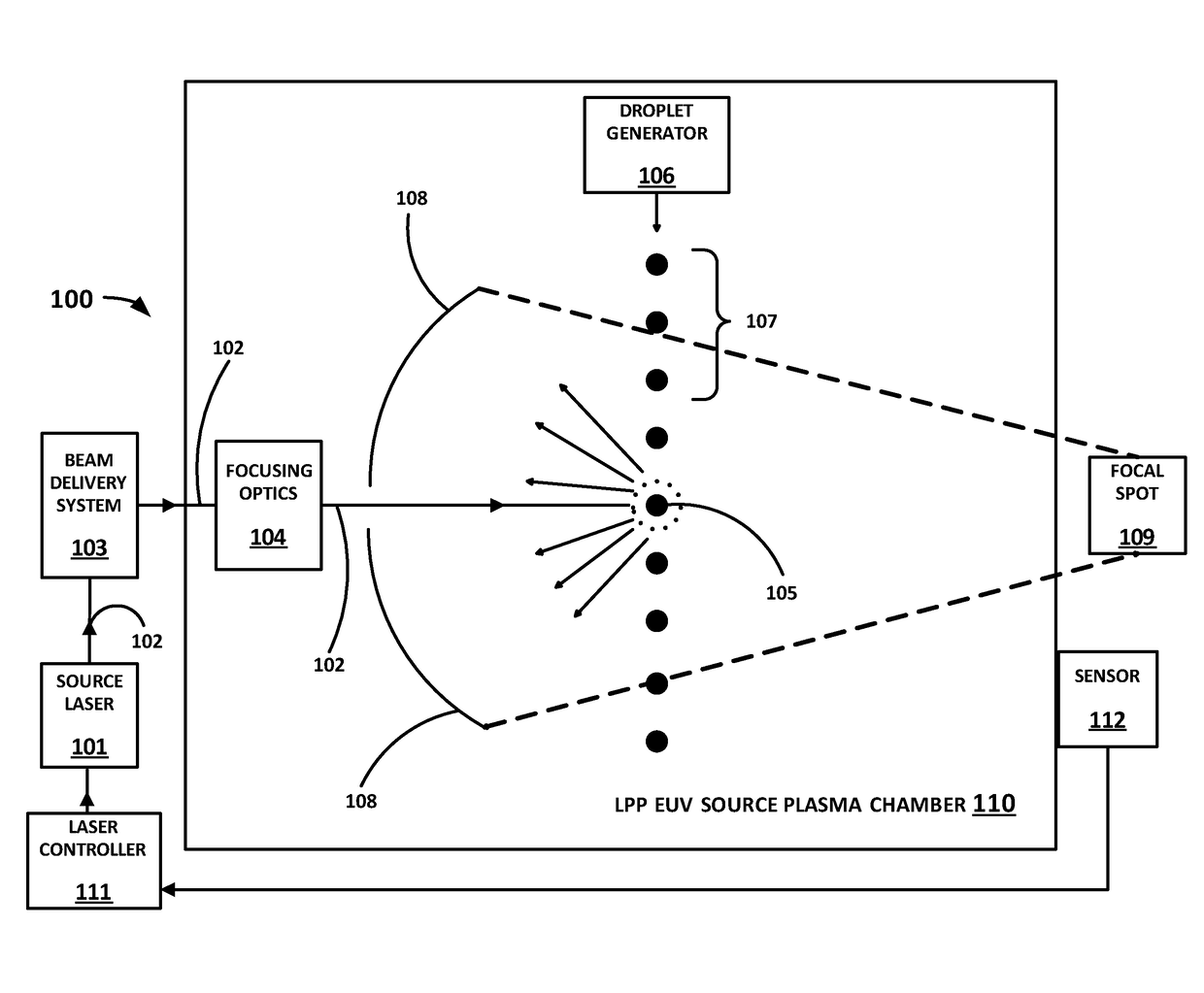
[0024]The present application describes a method and apparatus for improving the control of a dose of EUV radiation generated by a laser produced plasma (LPP) extreme ultraviolet (EUV) light source and applied to an item, such as a semiconductor wafer, being processed.

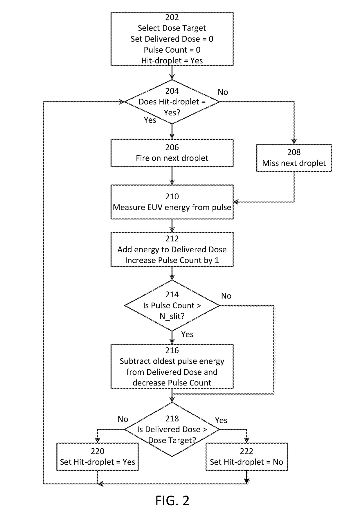
[0025]In one embodiment, a running total of the EUV energy generated over a number of laser pulses is measured. Once a certain predetermined number of pulses is exceeded, the energy from the oldest pulse within a moving window of the predetermined number of pulses is dropped from the running total, so that thereafter the running total is from the most recent predetermined number of pulses. If the running total of the EUV energy exceeds a target dose, the next pulse is caused to not hit a droplet; since the energy from the oldest pulse is dropped, in most cases this will reduce the running total of EUV energy slightly and cause it to be below the target dose.

[0026]Keeping a running total of the EUV energy generated over...


PUM


Abstract

A method and apparatus for controlling a dose of extreme ultraviolet (EUV) radiation generated by a laser produced plasma (LPP) EUV light source. In one embodiment, a running total of the EUV energy generated over a predetermined number of laser pulses is measured; once that number of pulses is exceeded, the energy from the pulse immediately preceding the most recent predetermined number of pulses is dropped from the running total, so that the running total is from the most recent predetermined number of pulses. If the running total of the EUV energy exceeds a target dose, the next pulse is caused to not hit a droplet. This avoids the unwanted side effects of various prior art solutions, such as needing to miss many droplets in a row, or requiring the laser pulses to be shortened or reduced in power as in other prior art solutions.

Description

FIELD OF THE INVENTION[0001]The present invention relates generally to laser produced plasma (LPP) extreme ultraviolet (EUV) light sources. More specifically, the invention relates to a method and apparatus for improving the control of a dose of EUV radiation generated by an LPP EUV light source to be applied to an item, such as a semiconductor wafer, being processed.BACKGROUND OF THE INVENTION[0002]The semiconductor industry continues to develop lithographic technologies which are able to print ever-smaller integrated circuit dimensions. Extreme ultraviolet (“EUV”) light (also sometimes referred to as soft x-rays) is generally defined to be electromagnetic radiation having wavelengths of between about 5 and 120 nm. EUV lithography is currently generally considered to include EUV light at wavelengths in the range of about 10-14 nm, and is used to produce extremely small features, for example, sub-32 nm features, in substrates such as silicon wafers. These systems must be highly reli...

Claims


Application Information

Patent Timeline
IPC IPC(8): H05G2/00
CPCH05G2/003H05G2/008H05G2/005H05G2/006
Inventor ERSHOV, ALEXANDER IGOREVICH
Owner ASML NETHERLANDS BV
Learn More