The results would therefore be inaccurate for an inventory of the container because the reader would
record that the medications outside the container are inside the container when they actually are not.
The initial purpose of such systems was to reduce medication errors associated with manual distribution and the high cost of maintaining a large amount of inventory.
These tags are very low cost and are produced in enormous quantities.
Programming each one of the tags with information contained in the article to which they are attached involves further time and expense.
Another choice is an active RFID tag; however, such tags require an accompanying battery to provide power to activate the tag, thus increasing the expense of the tag and making them undesirable for use in a large number of applications.
Additionally, in the U.S. and in other countries, the frequency range within which such tags are permitted to operate is limited.
At this frequency range, the electromagnetic energy is less affected by liquids and other
dielectric materials, but suffers from the limitation of a short interrogating distance.
Additionally,
metal surfaces of the enclosures present a serious obstacle for the RF signals that need to be exchanged between RFID readers and RFID tags, making RFID tags located behind those
metal surfaces difficult or impossible to detect.
In addition to the above, the detection range of the RFID systems is typically limited by
signal strength to short ranges, frequently less than about thirty centimeters for 13.56 MHz systems.
However, such an antenna may be unwieldy and may increase the range of the radiated power beyond allowable limits.
Furthermore, these reader antennae are often located in stores or other locations where space is at a premium and it is expensive and inconvenient to use such large reader antennae.
In another possible solution, multiple small antennae may be used but such a configuration may be awkward to set up when space is at a premium and when wiring is preferred or required to be hidden.
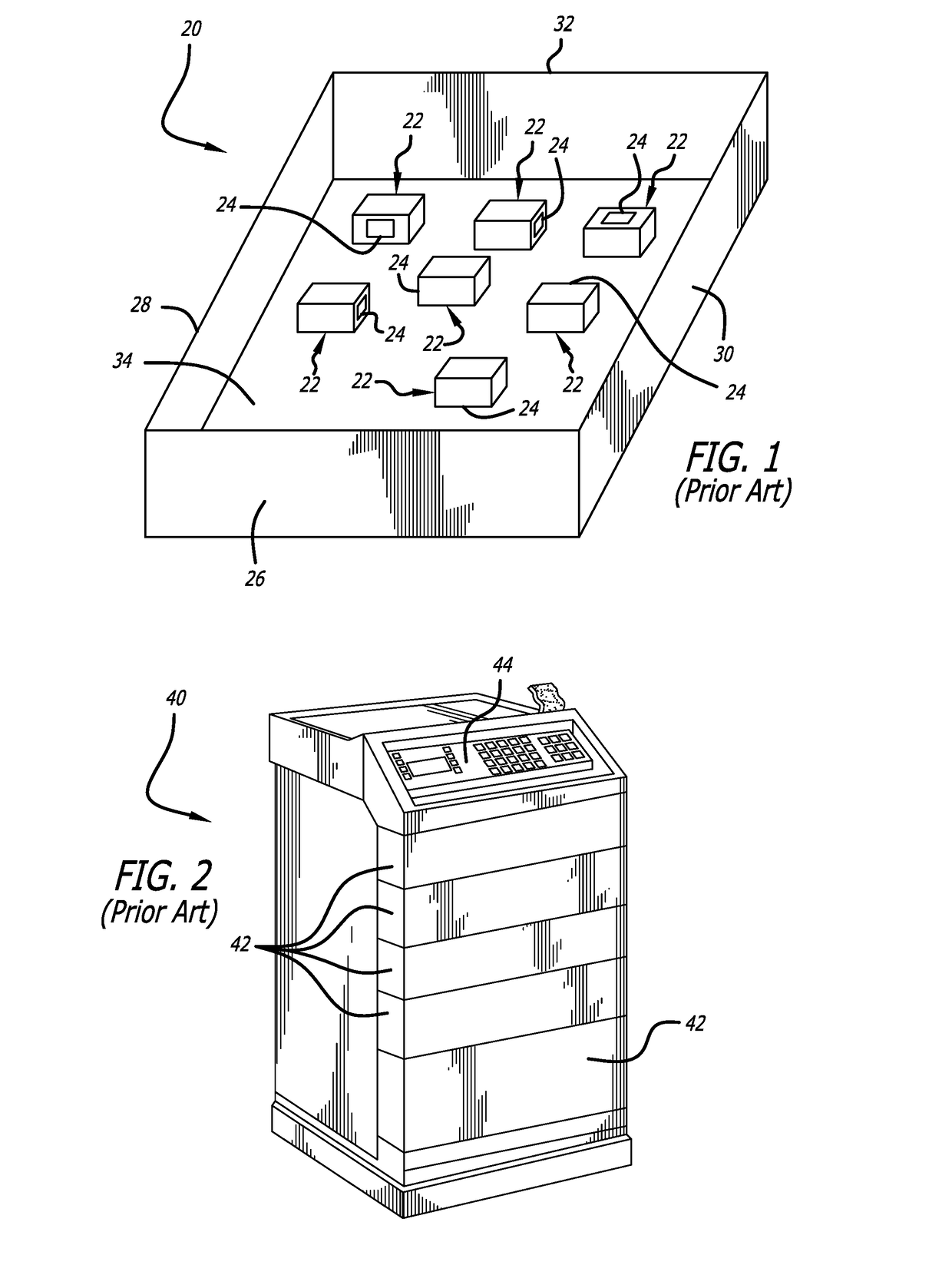
Cabinets such as these are typically made of
metal, which can make the use of an external RFID
system for identification of the stored articles difficult.
In some cases, such cabinets are locked due to the presence of narcotics or other medical articles or apparatus within them that are subject to a high theft rate.
Thus, manual identification of the cabinet contents is difficult due to the need to control access.
Providing an internal RFID
system in such a cabinet can
pose challenges.
In general, dead zones are areas in which the level of
coupling between an RFID reader antenna and an RFID tag is not adequate for the
system to perform a successful read of the tag.
Thus, articles placed in dead zones may not be detected thereby resulting in inaccurate tracking of tagged articles.
Often in the medical field, there is a need to read a large number of tags attached to articles in such an
enclosure, and as mentioned above, such enclosures have
limited access due to security reasons.
The use of high-power readers to locate and extract data from RFID tags is generally undesirable in health care facilities, although it may be acceptable in warehouses that are sparsely populated with workers, or in aircraft cargo holds.
Radiating a broad beam of EM energy at a large area, where that EM energy may stray into adjacent, more sensitive areas, is undesirable.
Additionally, this is a manual system that will require the services of one or more individuals, which can also be undesirable in facilities where staff is limited.
All of the foregoing can take significant amounts of time.
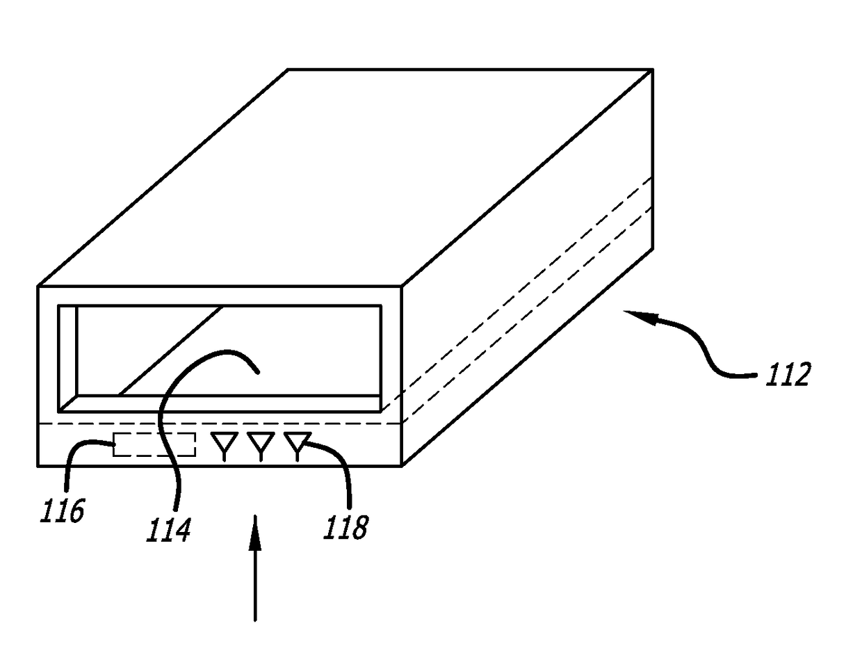
A problem often arises where only the RFID tags attached to medical articles located in a particular location or container are to be read for inventory purposes.
While this system works well, problems arise when the activating RFID beam was strong enough to reach the RFID tags on medical articles that are stored in the locality of the tray but are not in the tray.
If one of those medical articles having an activated tag that is located outside the tray is determined to be expired, inaccuracy and time
wasting can result.
However, the radiated
signal will leak out of gaps, slots, openings, and other discontinuities that may be present in the RF shielded container.
These leaked signals are free to radiate in open space and may cause the activation of remote RFID tags.
However, it has been found that gaps or apertures and other openings can be very difficult to avoid.
Seams needed for manufacturing,
doors, drawers, and other openings made for various purposes penetrate the shielded container, which can lower the shielding performance of the container.
Screws or rivets are less satisfactory methods to secure the seams because permanent low-impedance contact along the seams between the fasteners is difficult to maintain with these methods.
This can then solve the problem of inadvertently reading remote RFID tags that are not in the container; however, making and distributing RF shielded containers have associated problems, some of which have been described above.
In medical applications, current systems used for tracking items with RFID technology consist of heavy, sometimes custom made, and more expensive, metal containers.
These metal containers are basic in design due to the cost and difficulty of shaping metal into aesthetically pleasing shapes.
The enclosures are fabricated by hand and therefore are expensive.
The sheet metal enclosures are also relatively heavy and therefore require expensive hardware for stacking multiple units or to
mount under cabinets, desks, and work stations.
Heavy metal administration or storage cabinets can be difficult to move and place in desired positions and present an even more difficult handling situation when they are required to be stacked on one another.
A requirement to manufacture different sizes of RFID tracking containers, one for each possible use, can be very expensive and inefficient.
Similarly, having to use a shielded container that is much too large for the particular application at hand is inefficient and can be expensive.

