Method for making hybrid ceramic/metal, ceramic/ceramic body by using 3D printing process

a technology of ceramic/ceramic body and 3d printing process, which is applied in the direction of blade accessories, machines/engines, domestic applications, etc., can solve the problems of complex geometries, too brittle ceramics for use in certain applications, and weak shearing and tension of ceramics, etc., and achieves the requirement of more complicated and intricate internal geometries

Active Publication Date: 2017-07-13
GENERAL ELECTRIC CO
View PDF26 Cites 7 Cited by
  • Summary
  • Abstract
  • Description
  • Claims
  • Application Information

AI Technical Summary

Problems solved by technology

Many modern engines and next generation turbine engines require components and parts having intricate and complex geometries, which require new types of materials and manufacturing techniques.
However, ceramics are also known to be weak in shearing and tension, and too brittle for use in certain applications.
Conventional techniques for manufacturing engine parts and components involve the laborious process of investment or lost-wax casting.
However, these post c

Method used


Image

  • Method for making hybrid ceramic/metal, ceramic/ceramic body by using 3D printing process
  • Method for making hybrid ceramic/metal, ceramic/ceramic body by using 3D printing process
  • Method for making hybrid ceramic/metal, ceramic/ceramic body by using 3D printing process

Examples


example 1

General Procedure

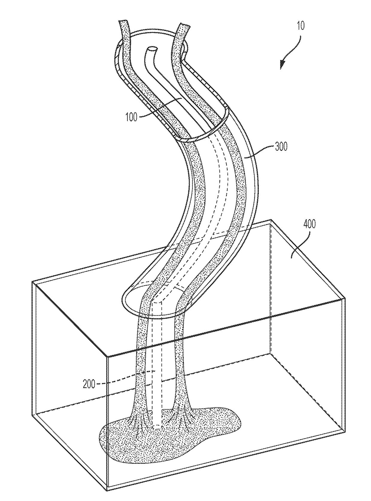
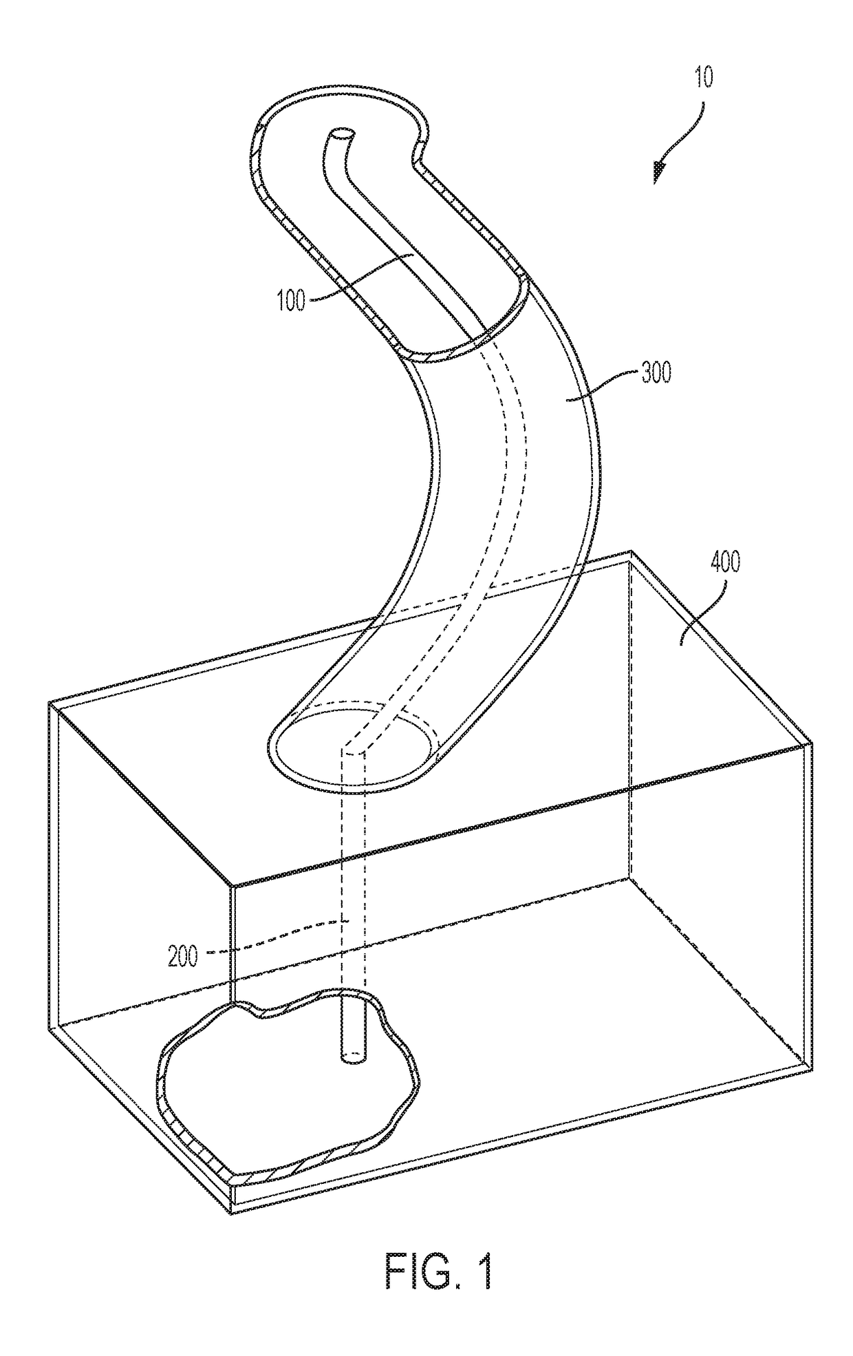
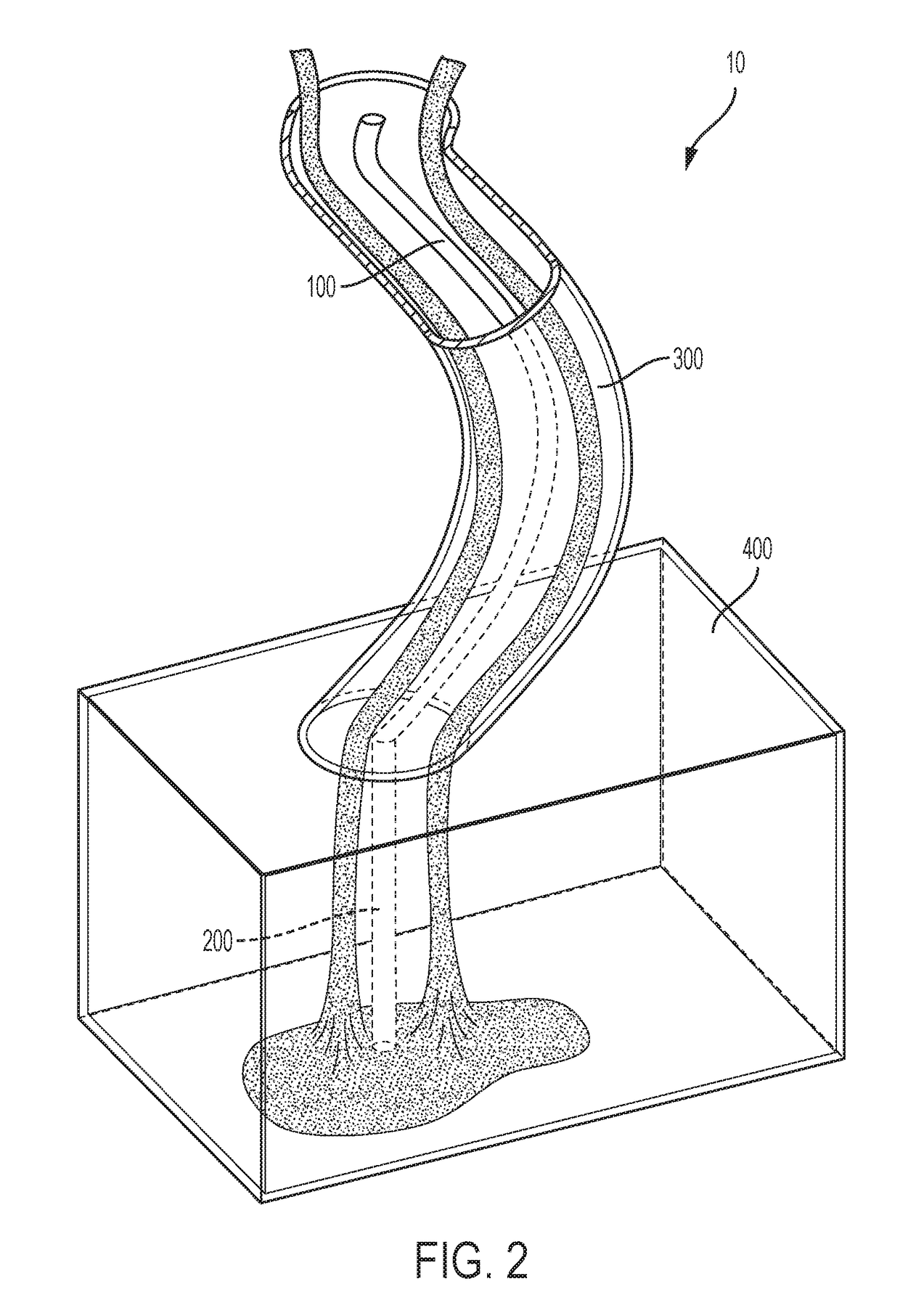
[0081]First phase: To produce a ceramic structure in accordance to the method of the present invention, a photopolymer printer (e.g., 3D systems VisiJet) is used to fabric a plastic die having a structure forming an external surface and an internal hollow cavity. The internal hollow cavity will be fabricated by printing a strcture with an internal diameter of 0.016 inch and a depth of 0.5 inch to 1 inch long. The plastic die is produced using a tipcap pin having 0.045 inch diameter through an additive printing process. A slurry of ceramic materials, such as siloxane, silica, zircon, alumina, yttria is injected into the portion of the plastic die representing the external surface such that the slurry forms around the internal hollow cavity. Following one or more rounds of sintering at a temperature of about 1600° C., the green body is cured and the plastic die is removed or burned off leaving an internal hollow cavity having a diameter of approximately 0.016 inches a...

example 2

Alumina Rod Insertion

[0084]A plastic die is printed in accordance with the procedure set forth in Example 1. The plastic die will be designed to include both an external surface and an internal cavity having an outside diameter of 0.013 inch and a depth of 0.5 inch. As described before, a ceramic slurry is injected into the external portion of the plastic die. The ceramic portion now within the external portion of the die is heated to a temperature of 500° C. to cure the ceramic matrix as well as to burn off the plastic die. An alumina rod having a diameter of approximately 0.011 inch and a length of 0.5 inch that is coated in ceramic-based slurry is inserted into the internal cavity created by the internal hollow cavity. The combined ceramic and alumina rod is heated at a temperature of approximately 1600° C. to sinter the ceramic matrix and alumina rod, where the sintering creates a bond at the interface of the matrix and the rod. The resulting product is a reinforced ceramic body...


PUM

PropertyMeasurementUnit
Temperatureaaaaaaaaaa
Depthaaaaaaaaaa

Abstract

This invention relates to a product and a method of preparing ceramic and/or ceramic hybrid materials through the construction of a printed die. The printed die being made by three dimensional printing or additive manufacturing processes possesses both an external geometry and an internal geometry.

Description

INTRODUCTION[0001]This invention generally relates to reinforced ceramic or ceramic composite materials, and methods for preparing said materials, components, and / or structures through additive printing techniques, where the composite materials have both internal and external geometries, and more particularly to methods of using additive printing technologies to make functional composite or hybrid components.BACKGROUND[0002]The present invention generally relates to a method of using additive manufacturing processes to produce reinforced ceramic or ceramic composite materials, such as but not limited to ceramic-ceramic or ceramic-metal hybrid (i.e., cermet) materials.[0003]Many modern engines and next generation turbine engines require components and parts having intricate and complex geometries, which require new types of materials and manufacturing techniques. One such material includes ceramic components and parts, which reduce the need for cooling and are much lighter than conve...

Claims


Application Information

Patent Timeline
IPC IPC(8): B29C67/00F01D5/18B28B23/02B28B1/14B28B11/24
CPCB29C67/0051B28B1/14B28B11/24B28B23/02F01D5/18F05D2300/603B29K2101/12B29L2031/757F05D2220/30F05D2230/211F05D2300/20B29K2101/10B33Y10/00B29C33/40C04B35/622C04B37/00C04B37/02C04B2235/6022C04B2237/343C04B2237/341B28B1/26B28B1/263B28B7/342B28B7/348B28B1/008C04B37/001C04B2237/84B32B18/00C04B35/111C04B35/14C04B35/48C04B35/505C04B37/021C04B2235/483C04B2235/6028C04B2235/94C04B2235/945C04B2237/345
Inventor YANG, XIPETERSON, BRIAN
Owner GENERAL ELECTRIC CO
Why Eureka
Try Eureka