Heat spreader and method for manufacturing the same

Active Publication Date: 2017-07-13
ALLIED MATERIAL
View PDF0 Cites 8 Cited by
  • Summary
  • Abstract
  • Description
  • Claims
  • Application Information

AI Technical Summary

Benefits of technology

[0023]According to the present invention, by setting the average thickness of the Cu—Mo layer with a small heat conductivity, of the heat spreader having a stacked structure, to less than or equal to 0.6 mm, the heat conductivity of the heat spreader in a thickness direction can be improved more than that of an existing one, and heat from an element can be removed further efficiently and immediately. In addition, by suppressing the variation in the thickness of the Cu—Mo layer to less than or equal to 0.1 mm to minimize the variation, local reduction in heat conductivity and local generation of thermal stress can be suppressed. Therefore, a heat spreader capable of removing h

Problems solved by technology

This is because, if the generated heat is not removed efficiently and immediately, the element itself may overheat and malfunction (thermally run away), or the element, a package which covers the element, or the like may be broken.
However, even when these elements are used, it is still required to remove he

Method used


Image

  • Heat spreader and method for manufacturing the same
  • Heat spreader and method for manufacturing the same

Examples


example 1

[0132](Formation of Porous Body)

[0133]Mo powder having an average particle size measured by the Fisher method of 3.9 μm was press-molded at a molding pressure of 100 MPa using a press machine, to fabricate a molded body in the shape of a plate having dimensions of 143 mm×174 mm×14.3 mm. The molded body had a molding density of 5.2 g / cm3.

[0134]Next, the molded body was sintered in a hydrogen atmosphere at 1000° C. for 1 hour using a firing furnace, to form a porous body. The porous body had an apparent density of 6.6 g / cm3 and a porosity of 35.3% by volume.

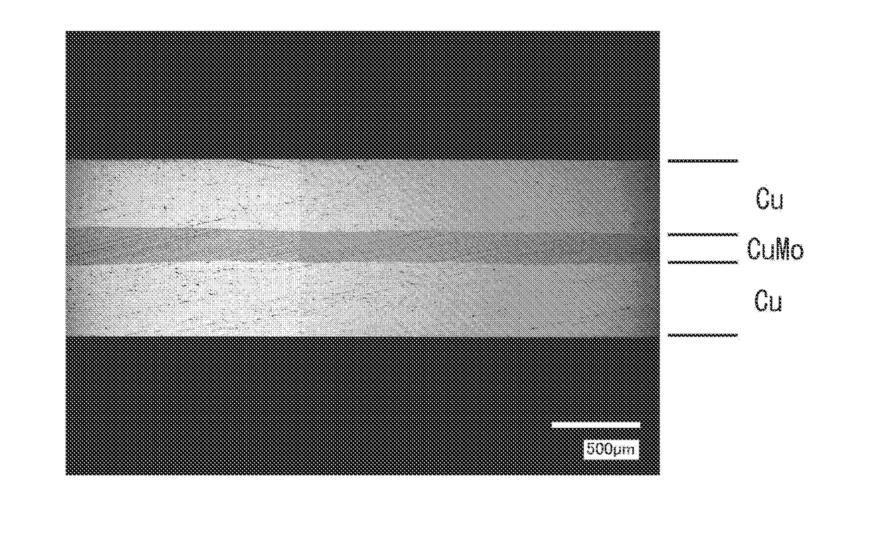
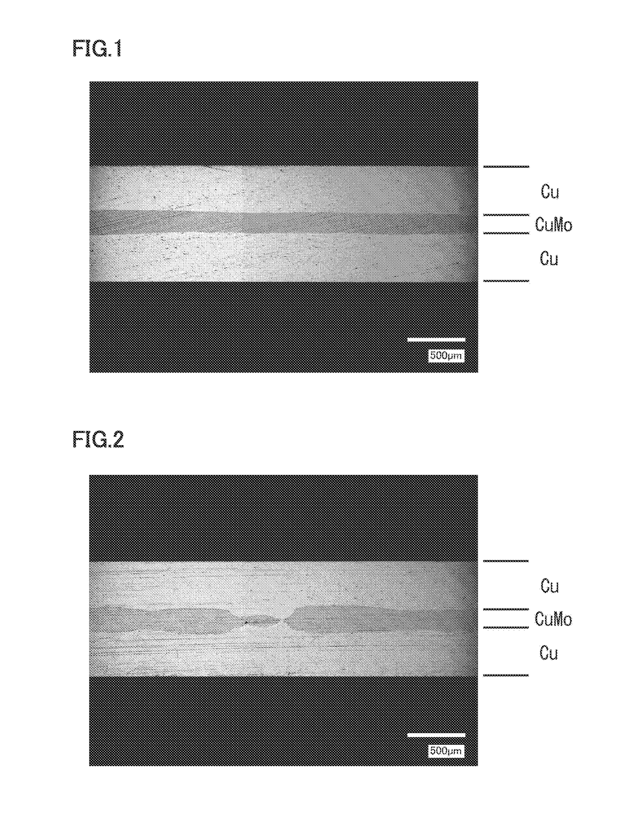
[0135](Fabrication of Cu—Mo Composite Body by Infiltrating Cu)

[0136]A Cu plate having a purity of 99.96% was placed on the above porous body, and they were heated in a hydrogen atmosphere at 1400° C. for 1 hour using the firing furnace, to infiltrate Cu into the porous body. Thereafter, extra Cu remaining on the surface of the porous body and the like was removed, to fabricate a Cu—Mo composite body having dimensions of 165 mm×131 ...

examples 9 and 10

[0156]Each heat spreader was manufactured as in Example 1, except for setting the total thickness of the stacked body including a Cu—Mo layer and two Cu layers and the total rolling reduction in the hot rolling and the cold rolling to values shown in Table 1.

examples 19 to 22

[0158]Each heat spreader was manufactured as in Example 1, except for using a Cu—Mo composite material having a ratio of Cu shown in Table 2.


PUM

PropertyMeasurementUnit
Lengthaaaaaaaaaa
Lengthaaaaaaaaaa
Lengthaaaaaaaaaa

Abstract

[Problem] To provide a heat spreader capable of removing heat from an element more efficiently and immediately than an existing one, and also capable of satisfactorily responding to further enhancement in performance and output of various apparatuses, and a method for efficiently manufacturing the same. [Solution] A heat spreader includes a Cu—Mo layer made of a Cu—Mo composite material and having an average thickness of less than or equal to 0.6 mm and a variation in thickness of less than or equal to 0.1 mm, and a Cu layer directly stacked on each of both surfaces thereof. A method for manufacturing the heat spreader includes planarizing a plate material of the Cu—Mo composite material constituting the Cu—Mo layer, and roll-bonding a Cu plate constituting the Cu layer to each of both surfaces thereof.

Description

TECHNICAL FIELD[0001]The present invention relates to a heat spreader for removing heat as efficiently as possible from an element which generates a large heat during operation in particular, and a method for manufacturing the same.BACKGROUND ART[0002]Removing heat as efficiently and immediately as possible is required for an element which generates a large heat during operation, such as a power semiconductor element used for drive control of an electric vehicle, a hybrid vehicle, or the like, a light emitting element such as a laser diode, a control element for a base station for mobile phones and the like, an image display element for a plasma display panel or the like, or a microprocessor unit for a computer.[0003]This is because, if the generated heat is not removed efficiently and immediately, the element itself may overheat and malfunction (thermally run away), or the element, a package which covers the element, or the like may be broken.[0004]In recent years, with enhancement...

Claims


Application Information

Patent Timeline
IPC IPC(8): F28F21/08B32B37/10B32B3/26B32B15/01B32B15/20
CPCF28F21/085B32B15/01B32B15/20B32B3/263B32B2311/12B32B2250/03B32B2307/302B32B2457/14B32B37/10B22F3/10B22F7/06C22C9/00C22C27/04H01L23/373H01L2924/0002F28F13/00F28F21/081H01L23/3735H01L23/3736H01L2924/00C23C26/00H05K7/2039
Inventor OKI, HIROAKIARIKAWA, TADASHIINABA, SHOUICHI
Owner ALLIED MATERIAL
Why Eureka
Try Eureka