
Power supply device

a power supply device and power supply technology, applied in the direction of dc network circuit arrangement, dc circuit to reduce harmonics/ripples, transportation and packaging, etc., can solve problems such as malfunction, and achieve the effects of reducing noise, restricting loss, and increasing the size of a circui

Inactive Publication Date: 2017-07-13
PANASONIC INTELLECTUAL PROPERTY MANAGEMENT CO LTD
View PDF8 Cites 8 Cited by
  • Summary
  • Abstract
  • Description
  • Claims
  • Application Information

AI Technical Summary

Benefits of technology

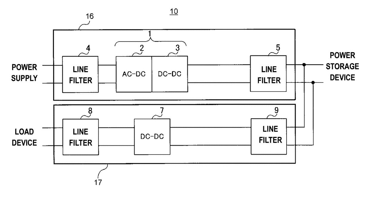
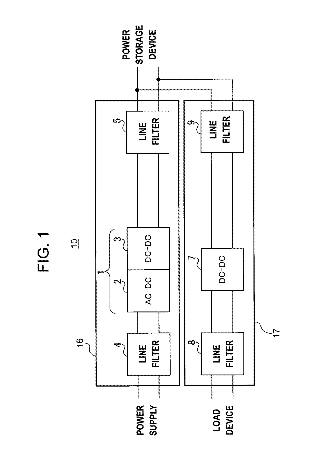
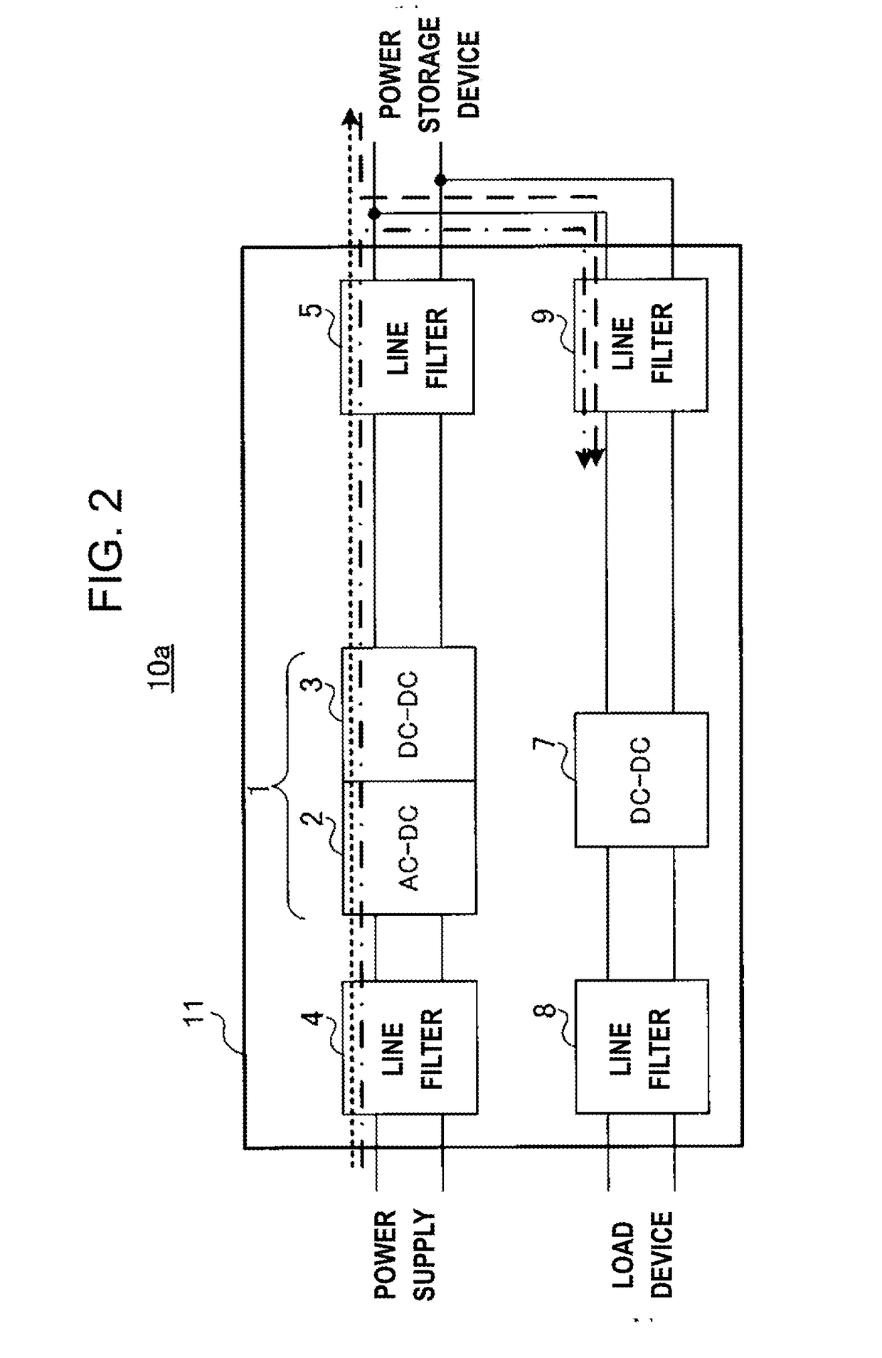
The present invention is about a power supply device that can reduce loss and keep the size of the circuit small. This device has two switching power supplies, a noise filter, and a shield. The noise filter reduces noise generated in the power supplies, while the shield blocks electromagnetic noise. The noise filter is positioned between the two switching power supplies, and nearer to the power storage device. The technical effect of this invention is that it minimizes power loss and circuit size.

Problems solved by technology

Since the switching power supply conducts the generated switching noise in an input direction and an output direction of the switching power supply, the switching noise has an effect on devices connected in each of the directions and thereby malfunction occurs.

Method used


Image

  • Power supply device
  • Power supply device
  • Power supply device

Examples


first modification example

[0050]FIG. 6 illustrates a configuration of power supply device 200 according to the first modification example. In FIG. 6, the same configurations as the above embodiment (FIG. 3) will be assigned with the same reference numerals, and description thereof will not be repeated.

[0051]In power supply device 200 illustrated in FIG. 6, electric compressor 201 is an example of the load device, and is configured with switching power supply 202 and motor 203. In addition, electric compressor 201 is covered with shield 108. Switching power supply 101 corresponds to the first switching power supply. Switching power supply 202 corresponds to the second switching power supply.

[0052]Switching power supply 202 is an inverter, converts DC power supplied from switching power supply 101 or the power storage device to AC power, and supplies the converted power to motor 203.

[0053]Motor 203 is driven by the AC power supplied from switching power supply 202, and is used for a heating or a cooling device...

second modification example

[0055]FIG. 7 illustrates a configuration of power supply device 300 according to the second modification example. In FIG. 7, the same configurations as in FIG. 3 and FIG. 6 will be assigned with the same reference numerals, and description thereof will not be repeated.

[0056]Power supply device 300 illustrated in FIG. 7 includes a plurality of load devices, each of which has the configuration illustrated in FIG. 3 and the configuration illustrated in FIG. 6. Specifically, power supply device 300 is mainly configured with switching power supply 101 that converts AC power supplied from the power supply to DC power, switching power supply 104 that converts a voltage value of DC power supplied from switching power supply 101 or the power storage device, and electric compressor 201 that is a load device driven with power supplied from switching power supply 101 or the power storage device being integrated. Switching power supply 101 corresponds to the first switching power supply. Switchi...


PUM


Abstract

A power supply device includes a first switching power supply that converts power of input power supply and supplies the converted power to a power storage device, a second switching power supply that converts power supplied from the first switching power supply or the power storage device and supplies the converted power to a load device, a noise filter that reduces noise generated in the first and second switching power supplies, and a shield against electromagnetic noise. The noise filter is provided between the first switching power supply and the power storage device, between the power storage device and the second switching power supply, and nearer to the power storage device than a branch point at which a power line from the first switching power supply to the power storage device intersects a power line from the second switching power supply to the power storage device.

Description

TECHNICAL FIELD[0001]The present invention relates to a power supply device having a plurality of switching power supplies.BACKGROUND ART[0002]When driven, a switching element used in a switching power supply generates harmonic noise and high-frequency noise (hereinafter, referred to as “switching noise”) according to a change in a current or a voltage. Since the switching power supply conducts the generated switching noise in an input direction and an output direction of the switching power supply, the switching noise has an effect on devices connected in each of the directions and thereby malfunction occurs. In the related art, a filter for removing the switching noise is provided in a power supply device as a measure to address the switching noise (for example, refer to PTLs 1 and 2).CITATION LISTPatent Literature[0003]PTL 1: Japanese Patent Unexamined Publication No. 11-89087[0004]PTL 2: Japanese Patent Unexamined Publication No. 2001-298952SUMMARY OF THE INVENTION[0005]The pres...

Claims


Application Information

Patent Timeline
Patent Type & Authority Applications(United States)
IPC IPC(8): H02J1/00H02P27/06H02J7/00H02M1/44H02M3/04H02M7/04
CPCH02J1/00H02M3/04H02M7/04H02J2007/0059H02M1/44H02P27/06H02J7/0052H02J1/02H02M1/12H02J2310/48H02J1/08H02M1/123H02J7/00H02J2207/20
Inventor MINATO, JUNJI
Owner PANASONIC INTELLECTUAL PROPERTY MANAGEMENT CO LTD
Learn More